Device at a portable display panel system

a display panel and device technology, applied in the field of display panel systems, can solve the problems of limiting the variation affecting the quality of the display panel system,

Active Publication Date: 2013-10-08
AHLBERG CHRISTIAN
View PDF6 Cites 3 Cited by
  • Summary
  • Abstract
  • Description
  • Claims
  • Application Information

AI Technical Summary

Benefits of technology

[0003]The object of the invention is to provide a device at a display panel system which eliminates the drawbacks mentioned above and which at the same time is easy to mount and dismount for transport as well as which is simple in its construction and function.BRIEF DISCLOSURE OF THE INVENTION
[0006]The upper and lower rods, which are connected with each other, have straight as well as bent as well as angled shapes and support the fabric panel having a graphic print or the like. As the upper and lower tubular rods, which are connected, have different shapes and are kept together by a combination of specially shaped end pieces and the string which has been put through all rods, a display panel is achieved which is both easy to handle, i.e. to mount and dismount and also easy to change as to shape.

Problems solved by technology

These systems are complex and hence difficult to mount rapidly or to change for adaption to new exhibition areas.
It is also associated with certain time consumption to raise / mount and dismount display panels of this kind.
Both these known panel systems consist of uniform upper and lower ribs, which limit the variation of the display panel system.

Method used


Image

  • Device at a portable display panel system
  • Device at a portable display panel system
  • Device at a portable display panel system

Examples


Embodiment Construction

[0020]Similar parts / details of the embodiments described and shown in the drawings have been denoted with the same reference numbers.

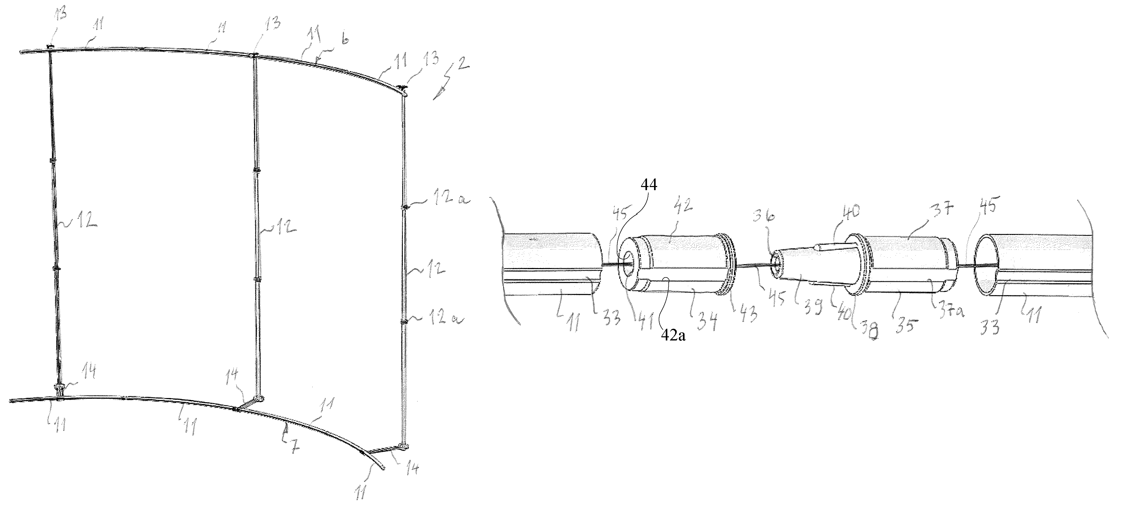
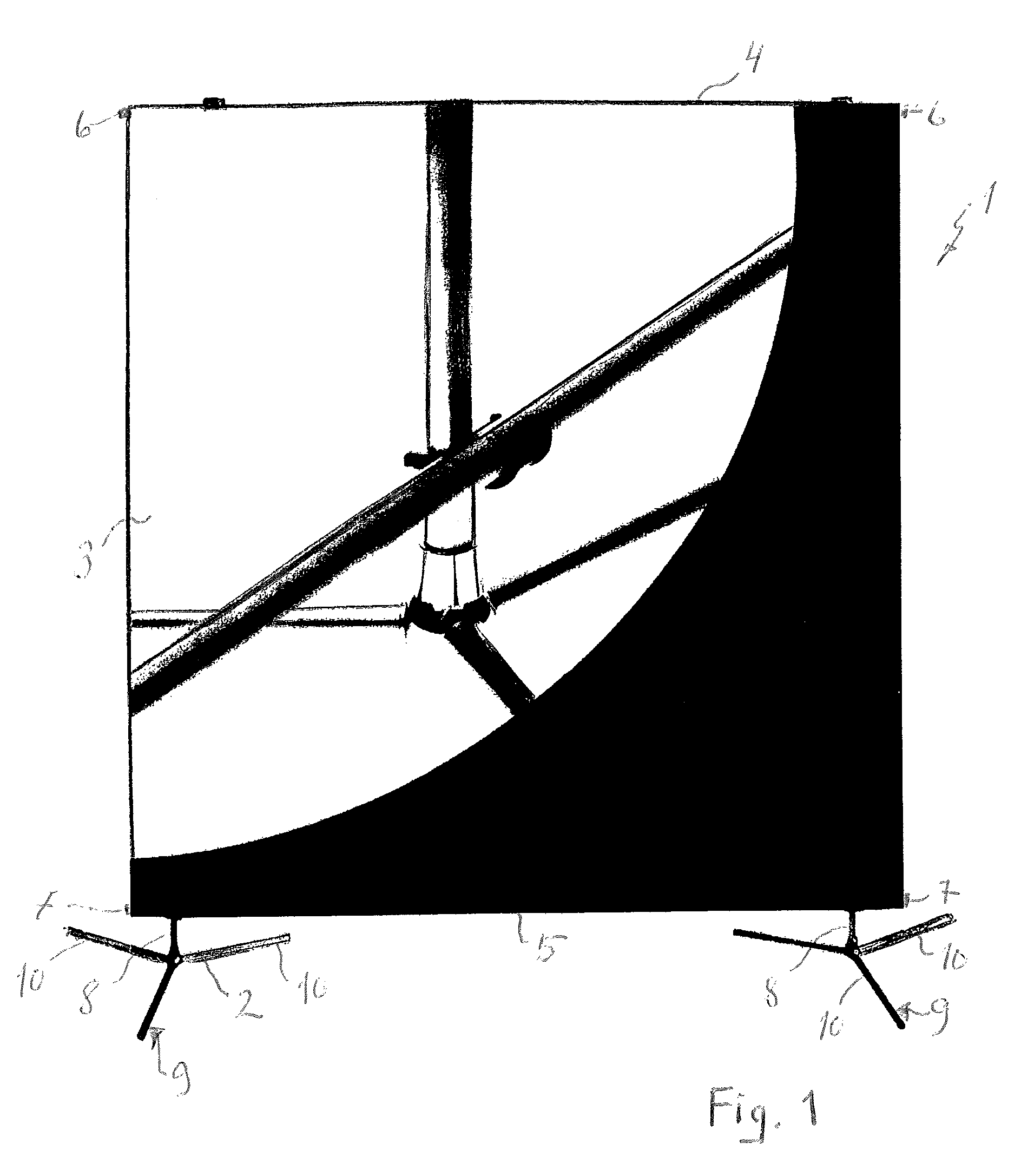
[0021]FIG. 1 shows a display panel system 1 with a supporting rack 2 and on the rack a supported and stretched cloth 3 or a panel of a flexible and elastic material, such as fabric, which has been provided with a graphic print. At the upper edge 4 and the lower edge 5 of the panel there are holder ribs 6 and 7, respectively, arranged in channels in the fabric which are sewn or manufactured in any other way, which ribs are included in the rack 2. The holder ribs 6, 7, which are parts of the device according to the invention, will be described more in detail below. As is partially shown in FIG. 1, the rack has telescopic props 8, which are attached to foldable floor supports 9 consisting of three legs 10 extending in three different directions.

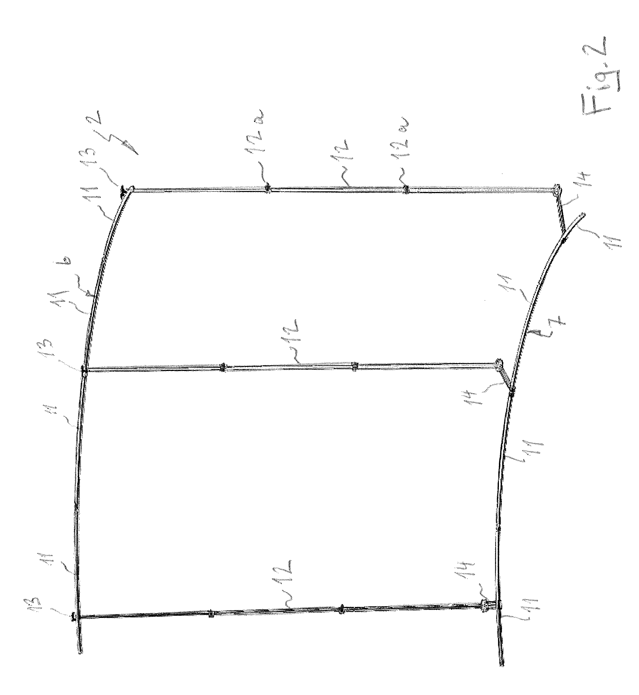
[0022]FIG. 2 shows a rack 2 for a panel 3 included in the display panel system 1 having a device according to th...


PUM


Abstract

Provided is a portable display panel system including a rack, upper and lower rods having pairs of upper and a lower holder ribs, and a cloth or a panel of a printable material. Each of the rods has a through-cavity. An elastic string extends through each of the upper and lower holder ribs and is attached to the outer ends of the outermost rods. Male and female couplings are arranged at the abutting ends of the rods arranged in pairs, which may be brought together in either two positions, which are turned by 180°, or four positions which are turned by 90° relative to each other. At least one pair of the rods are bent or angled.

Description

[0001]The present invention relates to a device at a portable display panel system according to the pre-characterizing portion of claim 1.PRIOR ART[0002]U.S. Pat. No. 6,718,669 describes a display panel system of the kind mentioned above. These systems are complex and hence difficult to mount rapidly or to change for adaption to new exhibition areas. It is also associated with certain time consumption to raise / mount and dismount display panels of this kind. An additional display panel system of this kind is shown in FR 2 759 880. Both these known panel systems consist of uniform upper and lower ribs, which limit the variation of the display panel system.THE OBJECT OF THE INVENTION[0003]The object of the invention is to provide a device at a display panel system which eliminates the drawbacks mentioned above and which at the same time is easy to mount and dismount for transport as well as which is simple in its construction and function.BRIEF DISCLOSURE OF THE INVENTION[0004]The obje...

Claims


Application Information

Patent Timeline
Patent Type & Authority Patents(United States)
IPC IPC(8): G09F17/00
CPCG09F15/0068G09F15/0062
Inventor AHLBERG, CHRISTIAN
Owner AHLBERG CHRISTIAN
Why Eureka
Try Eureka