
Container crane

A container and crane technology, applied in transportation and packaging, load hoisting elements, cranes, etc., can solve the problems of increasing the weight of the spreader, the space occupied by the steel wire rope, and reducing the lifting height, so as to reduce the height and weight of the overall structure, improve the Efficiency and safety of loading and unloading, the effect of reducing the lifting distance

Inactive Publication Date: 2010-06-30
游勇
View PDF1 Cites 2 Cited by
  • Summary
  • Abstract
  • Description
  • Claims
  • Application Information

AI Technical Summary

Problems solved by technology

[0002] Ordinary container cranes with walking trolleys, such as container loading and unloading bridges on the shore of ports, container gantry cranes on site, etc., are mainly composed of crane frames, wire rope reels, trolleys, wire ropes, spreaders and twist locks, etc. The existing problems: One is that the wire rope takes up a lot of space between the container spreader and the trolley. In some occasions where the space is limited, such as on a ship with limited headroom or when measuring instruments need to be added between the container and the trolley, It cannot be applied; the second is that the weight of the container spreader is very heavy, some of which weigh about 10 tons, and do reactive movement with the container back and forth, which wastes mechanical energy and electrical energy, and also increases the design weight of the crane structure, increasing the cost and cost; the third is Single or four steel wire ropes are used to lift the spreader and the container at or near the middle of the spreader. The stability of the container in the air is poor, which affects the container alignment, loading and unloading efficiency and safety.
Fourth, its own weight is huge
[0003] On April 23, 2008, the Chinese Patent Office announced the utility model patent "Short container spreader with weighing function", patent number 200720147642, trying to solve the above-mentioned first problem. Add a wing plate on each side, and use the wing plate instead of the wire rope to reduce the lifting height
However, this method reduces the lifting height to a limited extent. At the same time, using the wing plate instead of the steel wire rope reduces the lifting height while increasing the weight of the spreader and increasing the negative effect of the spreader's reactive movement with the container back and forth.

Method used


Image

  • Container crane
  • Container crane
  • Container crane

Examples


Embodiment 1

[0058] The bridge on the inland waterway is the main obstacle that affects the navigation of inland waterways. The headroom from the bridge to the water surface is certain. Therefore, in the design of container cranes on inland river container ships, ordinary container cranes with walking trolleys, trolleys and cranes are used. There is too much wasted space between tools, and the design is very difficult or even impossible. The present invention can solve this problem.

Embodiment 2

[0060] At present, most of the weight of container cargo is weighed by the ground scale. In many cases, the weighing needs to be completed when the crane is hoisted. At this time, one or more "hook scales" need to be added between the trolley and the spreader. "This scale needs to take up a lot of space, which is difficult to implement on ordinary container cranes. The present invention can solve this problem.

Embodiment 3

[0062] Large container cranes such as port container loading and unloading bridges and container yard gantry cranes have problems such as heavy cranes and spreaders, high energy consumption, poor aerial attitudes of spreaders and containers, poor stability, and low loading and unloading efficiency and safety. The present invention can overcome these drawbacks to a certain extent.


PUM


Abstract

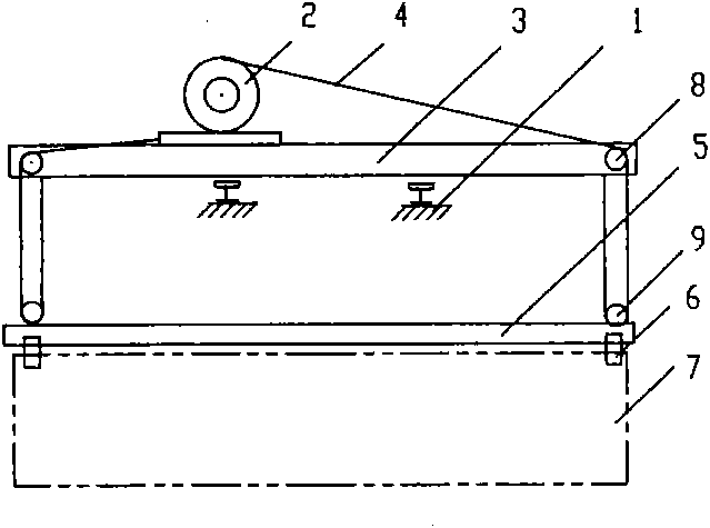
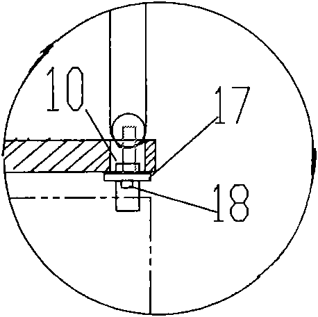
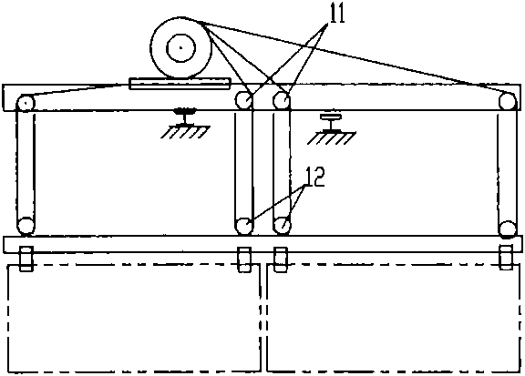
The invention relates to a container crane. A regular port shoreside container loading bridge, a container gantry crane and the like have the problems that a steel wire rope between a container spreader and a trolley takes up much space, the container spreader is heavy and consumes much energy, the container has poor stability in the air and the like. A new trolley and a new container spreader are provided in the invention to effectively solve the problems and have the advantages of simple structure, economy and practicability, applicability to both large and small containers and detachable container spreaders.

Description

Technical field [0001] The invention relates to a container crane. Background technique [0002] Ordinary container cranes with walking trolleys, such as port quayside container loading and unloading bridges, site container gantry cranes, etc., are mainly composed of crane frames, wire rope drums, trolleys, wire ropes, spreaders, and twist locks. The existing problems: One is that the wire rope between the container spreader and the trolley occupies a lot of space. In some occasions where space is limited, such as on a ship with restricted headroom or when measuring instruments need to be added between the container and the trolley, etc. Cannot be applied; second, the container spreader is very heavy, some weighing about 10 tons, and it does reactive movement back and forth with the container, which wastes mechanical energy and electrical energy, increases the design weight of the crane structure, and increases the cost and cost; Single or four steel wire ropes are used to lift ...

Claims


Application Information

Patent Timeline
IPC IPC(8): B66C17/20B66C1/10B66C13/04
Inventor 游勇
Owner 游勇
Learn More