Pour spout member for packaging bag

a technology of pour spout and packaging bag, which is applied in the direction of transportation and packaging, pliable tubular containers, locking devices, etc., can solve the problems of troublesome operation of pour spout opening, uncrafty, and easy twisted protrusion, so as to facilitate twisted off, easy twisted off, easy to rotate and twisted o

Active Publication Date: 2013-10-22
HOSOKAWA YOKO CO LTD
View PDF27 Cites 0 Cited by
  • Summary
  • Abstract
  • Description
  • Claims
  • Application Information

AI Technical Summary

Benefits of technology

[0026]According to the present invention, the pour spout member provided by the present invention comprises a base adapted to be attached to a packaging bag, a tubular neck having a tip opening sealed by a sealing member and a lid member having an upper end connected to the sealing member and covering an outer periphery of the tubular neck, wherein the lid member includes expandable lid segments having upper ends connected to a portion integral with the sealing member; and, between the expandable lid segments in collapsed state and a portion integral with the tubular neck, there is provided a rotation locking mechanism adapted for temporary restriction of the lid member. With such construction, the lid member is surely locked on the tubular neck by the rotation locking mechanisms so far as the paired expandable lid segments of the lid member mounted on the tubular neck are in collapsed state. Specifically, the lid member is locked on the tubular neck in the expanding direction as well as in the rotational direction and therefore it is not apprehended that the sealing member might be unintentionally opened, for example, in transit. In addition, the expandable lid segments of the lid member having been locked on the tubular neck by the rotation locking mechanisms may be released to easily twist off the sealing member having been fixed to the tubular neck without laying the user's hand on the tubular neck by rotating the lid member.
[0027]According to the present invention, the rotation locking mechanism temporarily locks the expandable lid segments. With such construction, the expandable lid segments having been locked on the tubular neck by means of the rotation locking mechanisms may be released in expansion direction to easily rotate the sealing member with the expanded slit segments held with the user's hand. Consequentially, the sealing member having been locked on the tubular neck can be easily rotated and twisted off without laying the user's hand on the tubular neck.
[0028]According to the present invention, the expandable lid segments of the lid member are provided at distal ends thereof with handgrips used to expand the lid segments. With such construction, the expandable lid segments can be easily expanded with the handgrips in the user's hand.
[0029]According to the present invention, wherein the distal ends of the respective expandable lid segments are provided with expansion restricting pieces by the intermediary of links; and, between the expansion restricting pieces and respective portions integral with the tubular neck there are provided with rotation locking mechanisms serving to prevent the expansion restricting pieces from being released until said links are broken. With such construction, the expandable lid segments f the lid member may be torqued against the effect of the expansion restricting pieces locked on the tubular neck by the rotation locking mechanisms to break off the links from the expansion restricting pieces and thereby to allow the lid member to be rotated. In this way, the sealing member having been fixed to the tubular neck can be easily rotated and twisted off without laying the user's hand on the tubular neck. Specifically, breaking off the expansion restricting pieces from the expandable lid segments of the lid member can demonstrate opening of the lid member and the state in which the expansion restricting pieces remain locked on the tubular neck by the intermediary of the links can demonstrate that the pour spout member is not in use.
[0030]According to the present invention, the expansion restricting pieces are connected to the distal ends of the respective expandable lid segments by the intermediary of the breakable links. With such construction, traces of separation between the expansion restricting pieces and the associated expandable lid segments can be left after the expansion restricting pieces have been separated from the associated expandable lid segments.
[0031]According to the present invention, the expansion restricting pieces remain on the tubular neck after the rotation locking mechanisms have released the expandable lid segments from the tubular neck. With such construction, the expandable lid segments can be reliably released from the expansion restricting pieces and the expansion restricting pieces left on the tubular neck visibly indicate that the pour spout member was used.

Problems solved by technology

With such arrangement, there is a problem that not only operation of opening the pour spout is troublesome but it is sanitarily apprehended that the user's hand might come in contact with the pour spout.
In the case of the pour spout member disclosed in Japanese Patent Application Laid-Open Publication No. 2006-62752), there is anxiety that the protrusion might be readily twisted off when the cap is unintentionally rotated, for example, in the course of transit and, in addition, such pour spout is not craft-friendly.
In the case of the pour spout member disclosed in Japanese Patent Application Laid-Open Publication No. 2006-341908), the pour spout is exposed and its construction is complicated and correspondingly troublesome for working.

Method used


Image

  • Pour spout member for packaging bag
  • Pour spout member for packaging bag
  • Pour spout member for packaging bag

Examples


embodiment 1

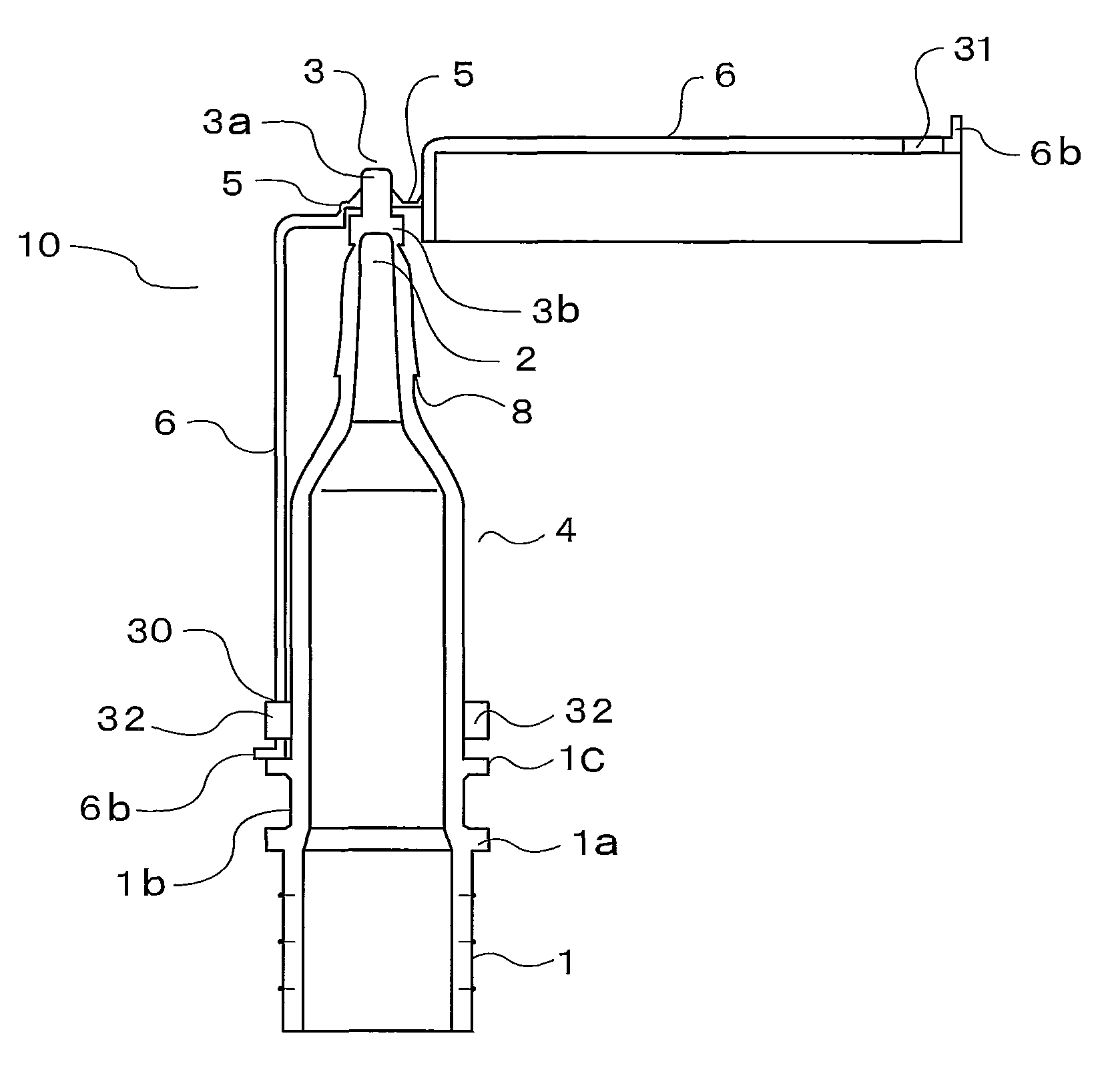
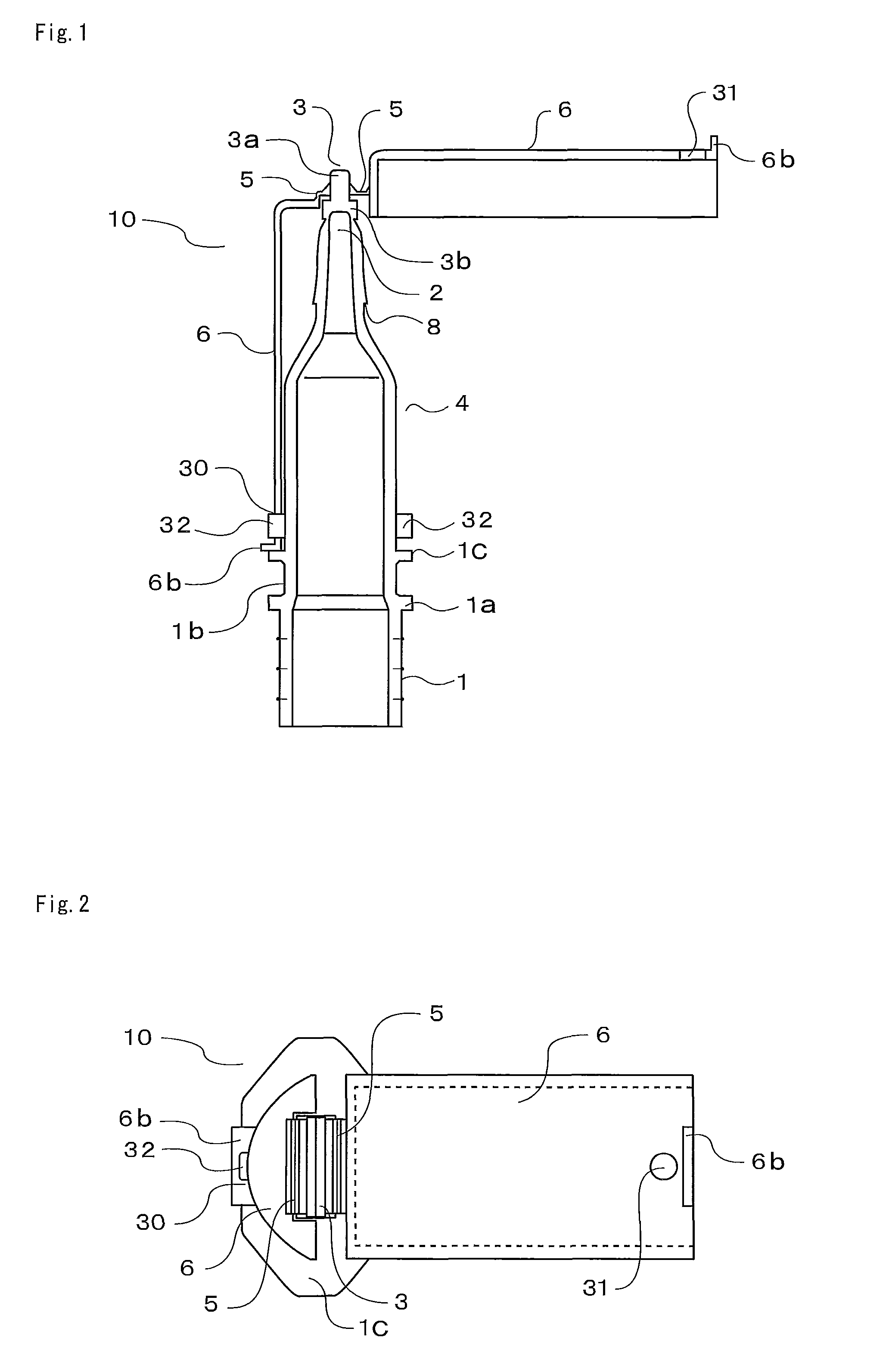
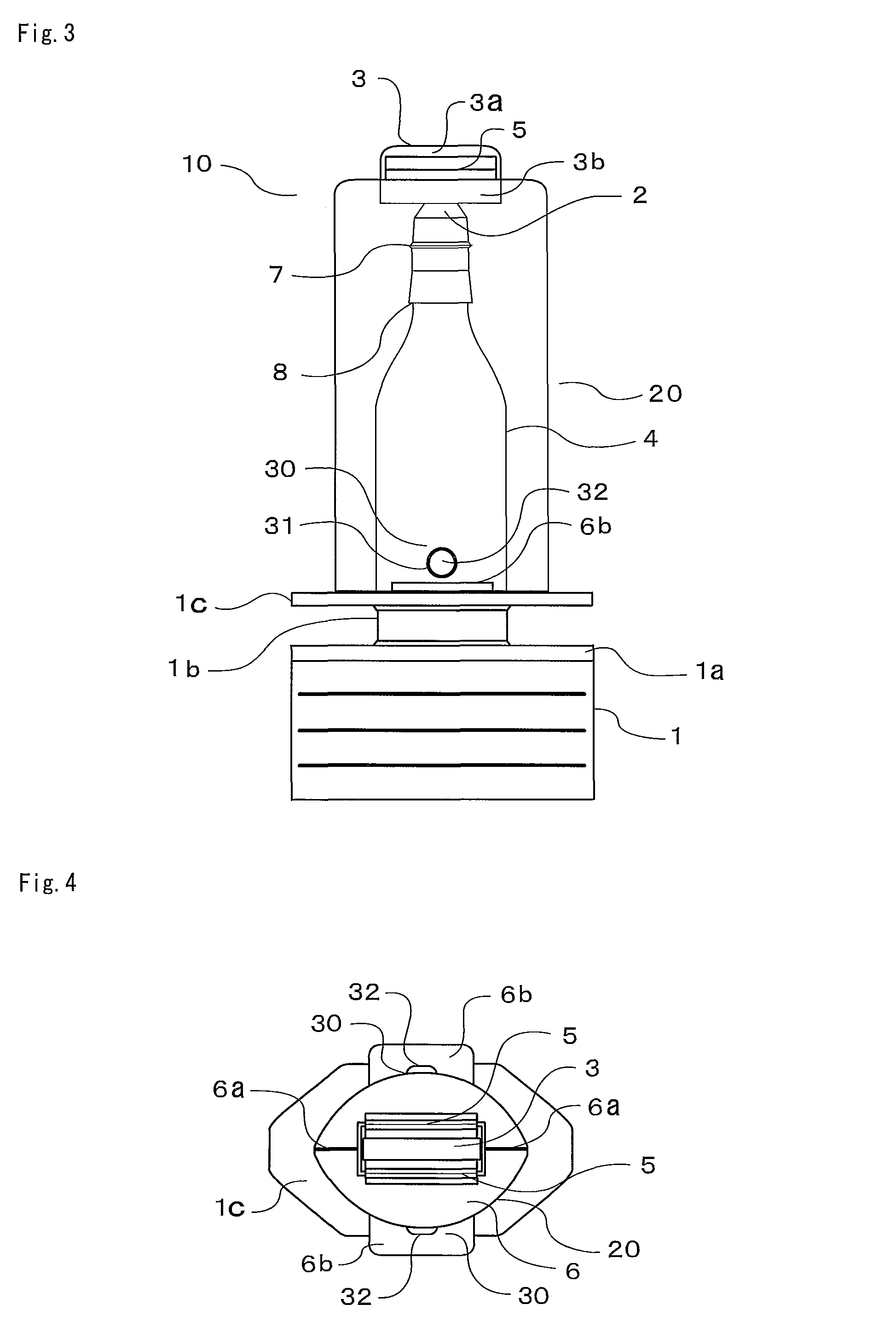
[0059]In an embodiment illustrated by FIGS. 1 through 7, a pour spout member 10 for packaging bag according to the present invention comprises a base 1 adapted to be heat-sealed to the packing bag, a tubular neck 4 having a tip opening 2 sealed by a sealing member 3 and a lid member 20 having its upper end joined to the sealing member 3 by connecting webs 5 so as to cover an outer periphery of the tubular neck 4. In the pour spout member 10, said lid member 20 includes a pair of lid segments 6 segmented in an expandable manner and having respective upper ends connected to said sealing member 3. Between the respective lid segments 6 in collapse state and said tubular neck 4, there are provided a rotation locking mechanism 30 adapted to prevent the lid member 20 from rotating and to temporarily lock expansion of the paired lid segments 6.

[0060]As will be apparent from FIG. 7, the base 1 is provided with an apical plate 1a horizontally extending and serving as a top plate of a pour spo...

embodiment 2

[0063]According to an embodiment illustrated by FIGS. 8 and 9, the paired expandable lid segments 6 are formed by segmenting a part of the lid member 20 along segmenting lines 6a, i.e., these paired expandable lid segments 6 partially define the lid member 20.

[0064]While not illustrated, such arrangement that the paired expandable lid segments 6 partially define the lid member 20 includes also an arrangement that respective upper ends of the expandable lid segments 6 are hinged to the lid member 20 which is integral with the sealing member 3 so that the expandable lid segments 6 partially defining the lid member 20 may be connected to the lid member 20 in expandable and collapsible manner.

[0065]Each of the respective segmenting lines 6a defining joints between the respective expandable lid segments 6 and the lid member 20 integral with the sealing member 3 may be formed with appropriate joint surfaces adapted to be detachably engaged with each other such as engage able L-shaped groo...

embodiment 3

[0069]the pour spout member 10 for packaging bag according to the present invention constructed as has been described above may be obtained, as illustrated by FIGS. 5 and 6, by a plastic monolithic injection molding using a molding tool 50. The molding tool 50 comprises right and left lateral molds 51 serving to, keeping the expandable lid segments 6 expanded in substantially horizontal state, mold right and left side surfaces of the tubular neck 4 and respective inner surfaces of the expandable lid segments 5 and vertically movable top and bottom forces 52, 53 serving to mold the sealing member 3 inclusive of the tubular neck interior 9 and the connecting webs 5 and respective outer surfaces of the expandable lid segments 6. Reference numeral 54 designates a stationary mold.

[0070]the lateral molds 51 are bilaterally symmetric and kept in closed positions as shown in FIG. 5 in the course of injection molding. When plastic material has been sufficiently cooled and hardened to be remo...


PUM

PropertyMeasurementUnit
shapeaaaaaaaaaa
forcesaaaaaaaaaa
inner diameteraaaaaaaaaa

Abstract

An improved pour spout member having a base attached to a packaging bag, a tubular neck having a tip opening sealed by a sealing member, and a lid member having an upper end connected to the sealing member and covering an outer periphery of the tubular neck. The lid member includes expandable lid segments having upper ends connected to a portion integral with the sealing member and, between the expandable lid segments in a collapsed state and a portion integral with the tubular neck, there is provided a rotation locking mechanism enabling temporary restriction of the lid member.

Description

CROSS-REFERENCE TO RELATED APPLICATION[0001]The present application claims priority under 35 U.S.C. §119 to Japanese Patent Application No. 2008-180937, filed Jul. 11, 2008, Japanese Patent Application No. 2008-310398, filed Dec. 5, 2008, and PCT / JP2009 / 003190 filed Jul. 8, 2009.BACKGROUND OF THE INVENTION[0002]1. Technical Field[0003]The present invention relates to a pour spout member heat-sealed to a packaging bag and used to pour fluent liquid out from the packaging bag.[0004]2. Related Art[0005]As the pour spout member adapted to be heat sealed to the packing bag, a pour spout member comprising a base adapted to be heat sealed to the packaging bag, a threaded tubular neck and a lid member adapted to be threadably mounted on the tubular neck is conventionally used (See Japanese Patent Application Laid-Open Publication No. 2000-142769).[0006]As another pour spout member of well known art, the pour spout member of a construction such that a tip opening of the pour spout is formed ...

Claims


Application Information

Patent Timeline
Patent Type & Authority Patents(United States)
IPC IPC(8): B65D5/72B65D25/40B65D47/10B65D55/02B65D35/38
CPCB65D75/5883
Inventor MORIYAMA, YUICHIROSHIRAI, KAZUYOSHITANAKA, YASUMASASHINOHARA, TOMONARIYOSHIDA, TOSHIHARUOOMORI, MAYUMITSUTSUMI, TAKESHI
Owner HOSOKAWA YOKO CO LTD
Why Eureka
Try Eureka