Patello-femoral milling system

a technology of patello-femoral and milling system, which is applied in the field of guided orthopedic milling system, can solve the problems of improper articulation and dislocation of the femur

Active Publication Date: 2013-10-22
ZIMMER INC
View PDF79 Cites 7 Cited by
  • Summary
  • Abstract
  • Description
  • Claims
  • Application Information

AI Technical Summary

Problems solved by technology

If the femoral trochlea becomes damaged due to disease or trauma, for example, the patella may articulate improperly across the femoral trochlea and may dislocate from the femur.

Method used


Image

  • Patello-femoral milling system
  • Patello-femoral milling system
  • Patello-femoral milling system

Examples


Embodiment Construction

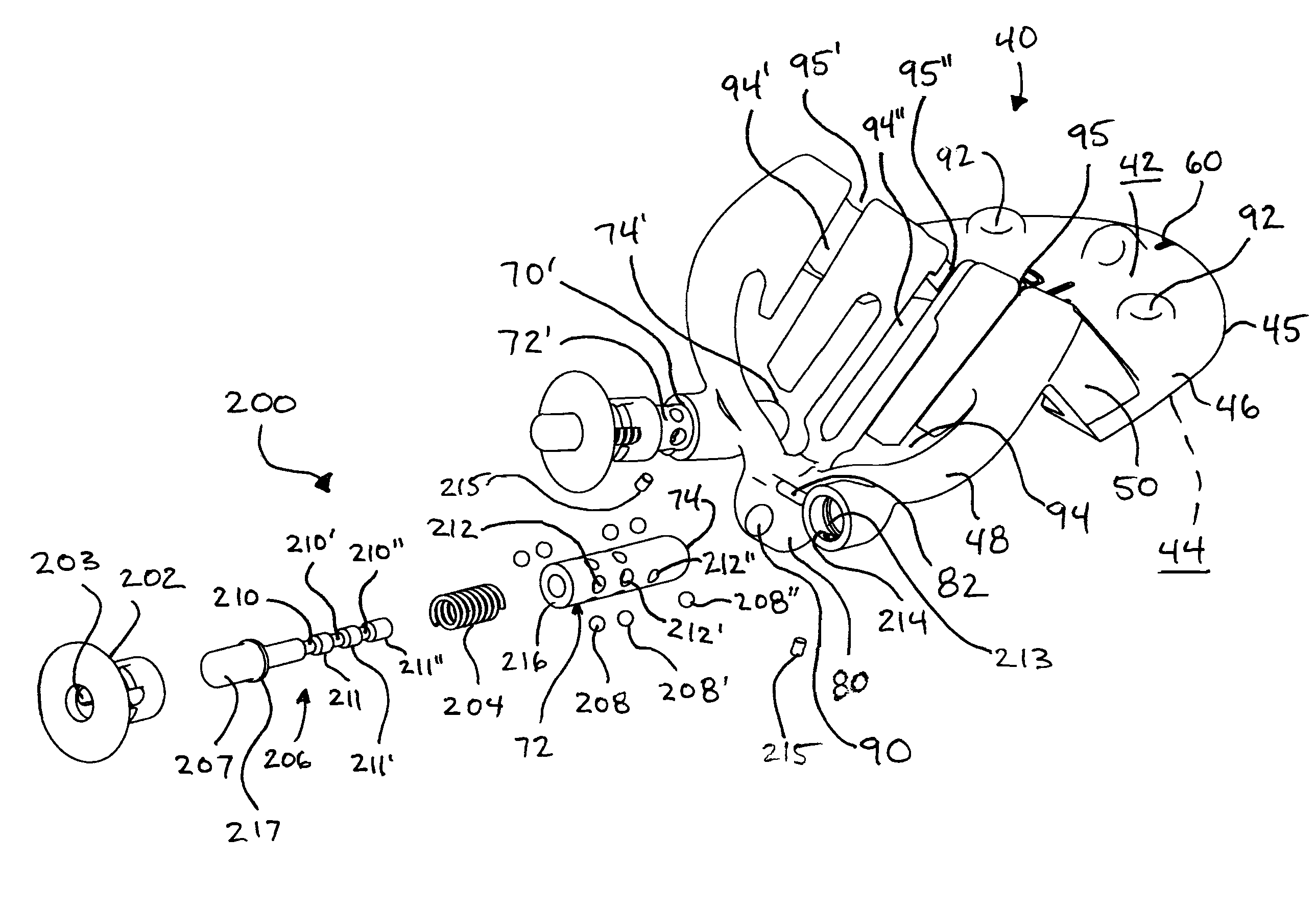
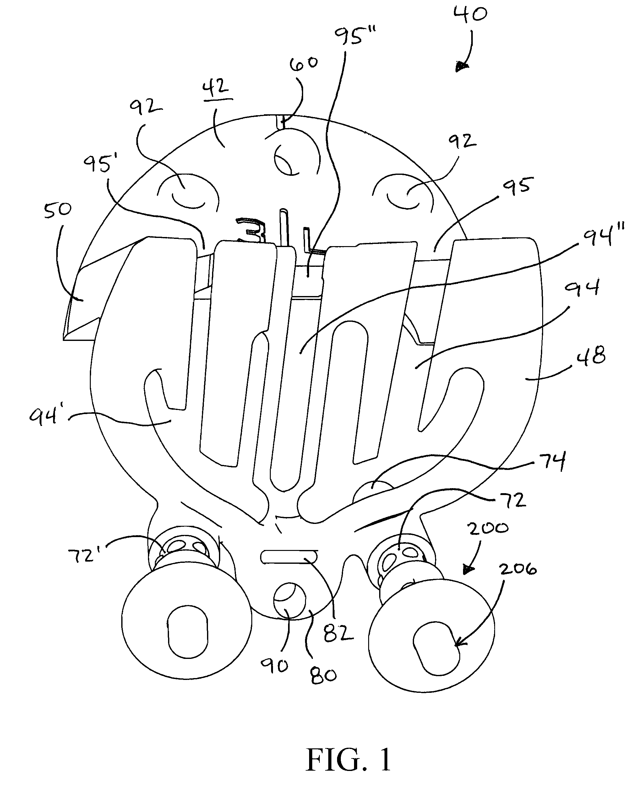
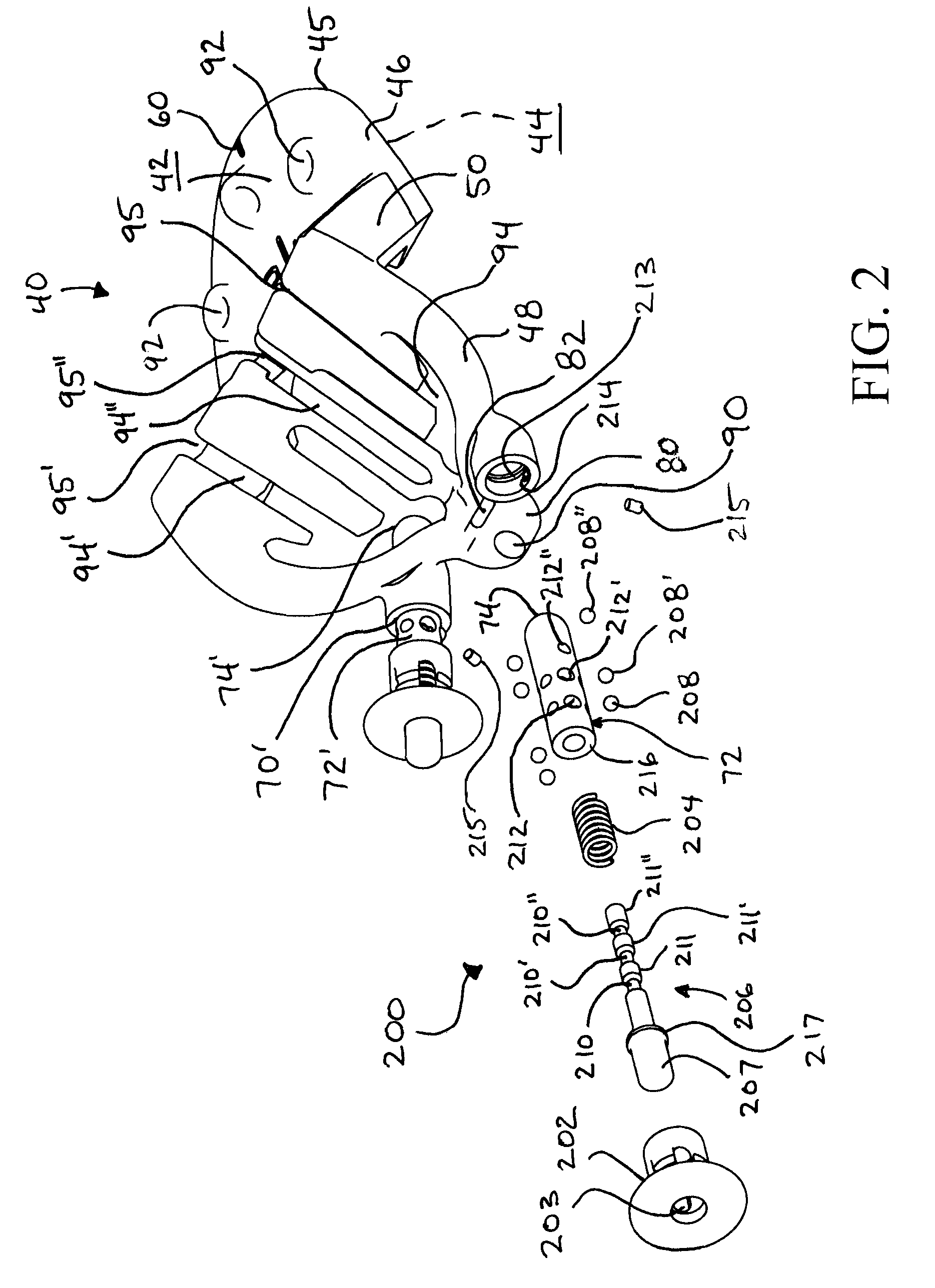
[0040]Referring to FIGS. 4, 7 and 9 orthopedic system 10 is provided for preparing femur 12 to receive a femoral trochlea prosthesis (not shown). Although orthopedic system 10 is described and depicted herein as being used to prepare femur 12 to receive a femoral trochlea prosthesis, orthopedic system 10 may be used to prepare other anatomical structures to receive a prosthesis, such as the tibia, fibula, radius, ulna, clavicle, and other bones. Femur 12 includes distal end 14, anterior surface 16 and posterior surface 18. Distal end 14 of femur 12 includes medial condyle 20, lateral condyle 22, and intercondylar notch 24 located between medial condyle 20 and lateral condyle 22. Anterior surface 16 of femur 12 includes trochlea or trochlear groove 26 located between medial condyle 20 and lateral condyle 22. During flexion and extension of the knee, a patella (not shown) glides across anterior surface 16 of femur 12 in trochlear groove 26. Although femur 12 is illustrated as a left f...


PUM


Abstract

An orthopedic system prepares a surface of an anatomical structure to receive an orthopedic prosthesis. A method for using the same is also disclosed. The orthopedic system includes a surgical instrument and a guide. The guide includes an anterior portion and a distal portion that is at least partially elevated relative to the anterior portion. The distal portion includes at least one track that is sized to receive the surgical instrument while preparing the surface of the anatomical structure.

Description

CROSS-REFERENCE TO RELATED APPLICATION[0001]This application claims the benefit of U.S. Provisional Patent Application Ser. No. 61 / 098,352, filed Sep. 19, 2008, the disclosure of which is expressly incorporated herein by reference in its entirety.BACKGROUND[0002]1. Field of the Invention[0003]The present invention relates to a guided orthopedic milling system. More particularly, the present invention relates to a guided orthopedic milling system for preparing a surface of an anatomical structure to receive an orthopedic prosthesis, and to a method for using the same.[0004]2. Description of the Related Art[0005]During flexion and extension of the knee, the patella glides across the front of the femur in a shallow groove, referred to as the femoral trochlea. If the femoral trochlea becomes damaged due to disease or trauma, for example, the patella may articulate improperly across the femoral trochlea and may dislocate from the femur. Disease and trauma affecting the patello-femoral jo...

Claims


Application Information

Patent Timeline
Patent Type & Authority Patents(United States)
IPC IPC(8): A61B17/00A61F2/00A61B17/60A61F5/00A61B17/58
CPCA61B17/1675A61B17/1764A61B17/1767
Inventor MAY, JUSTIN J.DETWEILER, JASON F.PARISI, RAYMOND C.GRINER, ADAM M.FARLING, TOBY N.
Owner ZIMMER INC
Why Eureka
Try Eureka