Incubator

a technology of incubator and incubator chamber, which is applied in the field of incubator, can solve problems such as user troubl

Inactive Publication Date: 2013-10-22
PANASONIC HEALTHCARE HLDG CO LTD
View PDF4 Cites 3 Cited by
  • Summary
  • Abstract
  • Description
  • Claims
  • Application Information

AI Technical Summary

Problems solved by technology

In Patent Document 2, the sterilization within the chamber is performed using the sterilizing gas generating device, the sterilizing gas generating device needs to be brought into the chamber, which causes the user to take trouble every time the sterilization processing is performed.

Method used


Image

  • Incubator
  • Incubator
  • Incubator

Examples


first embodiment

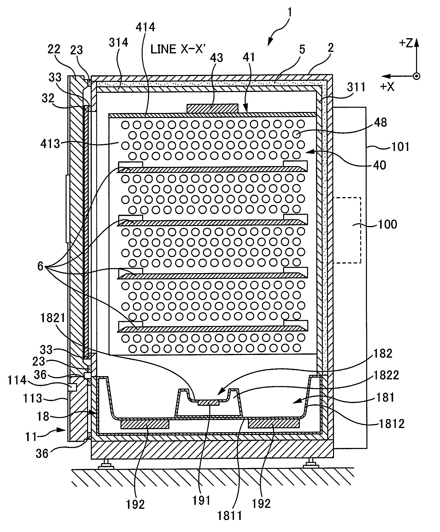
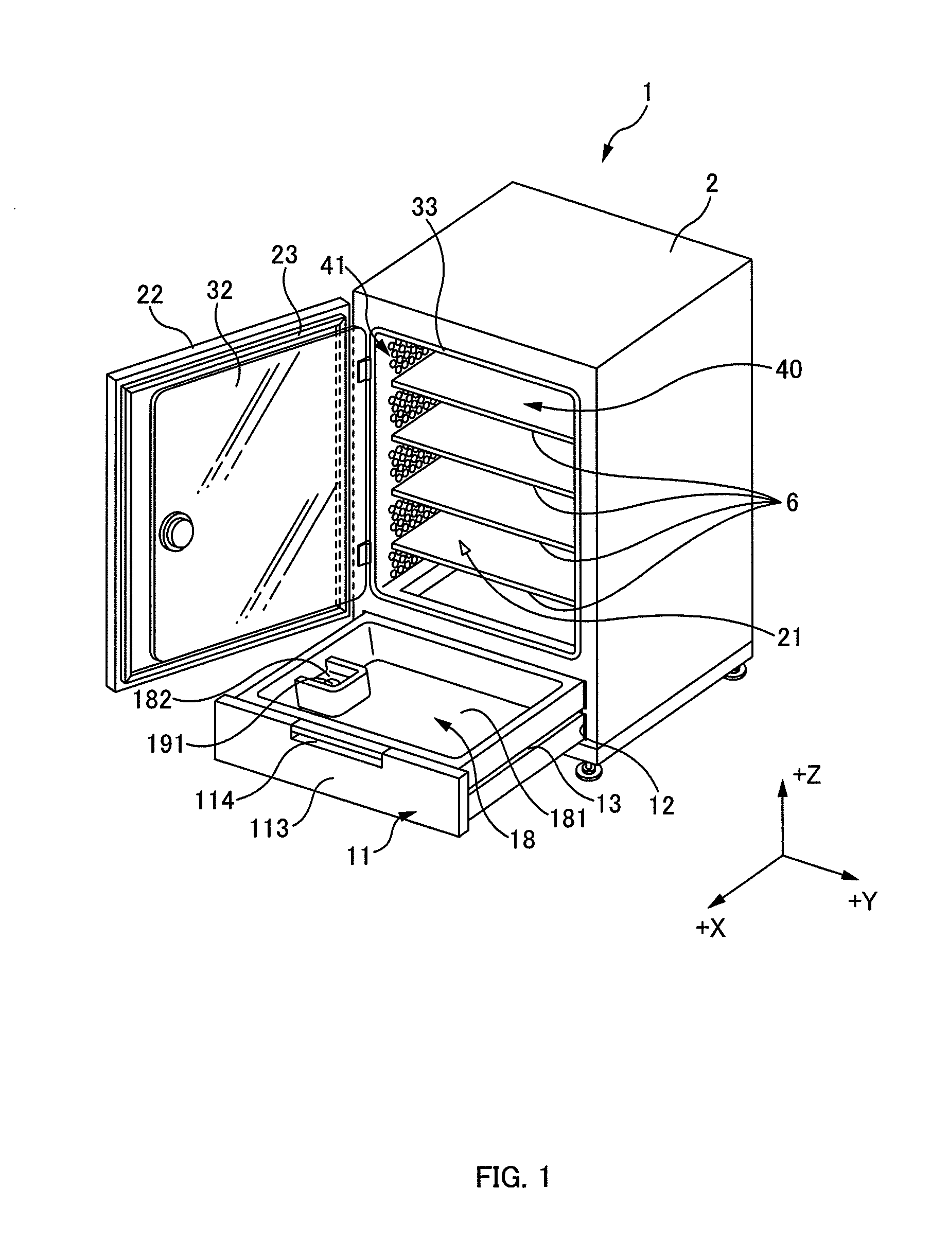
[0028]FIGS. 1 to 4 depict an incubator 1 which is to be described as a first embodiment of the present invention. In the following description, a coordinate system is to be set in directions indicated in these drawings.

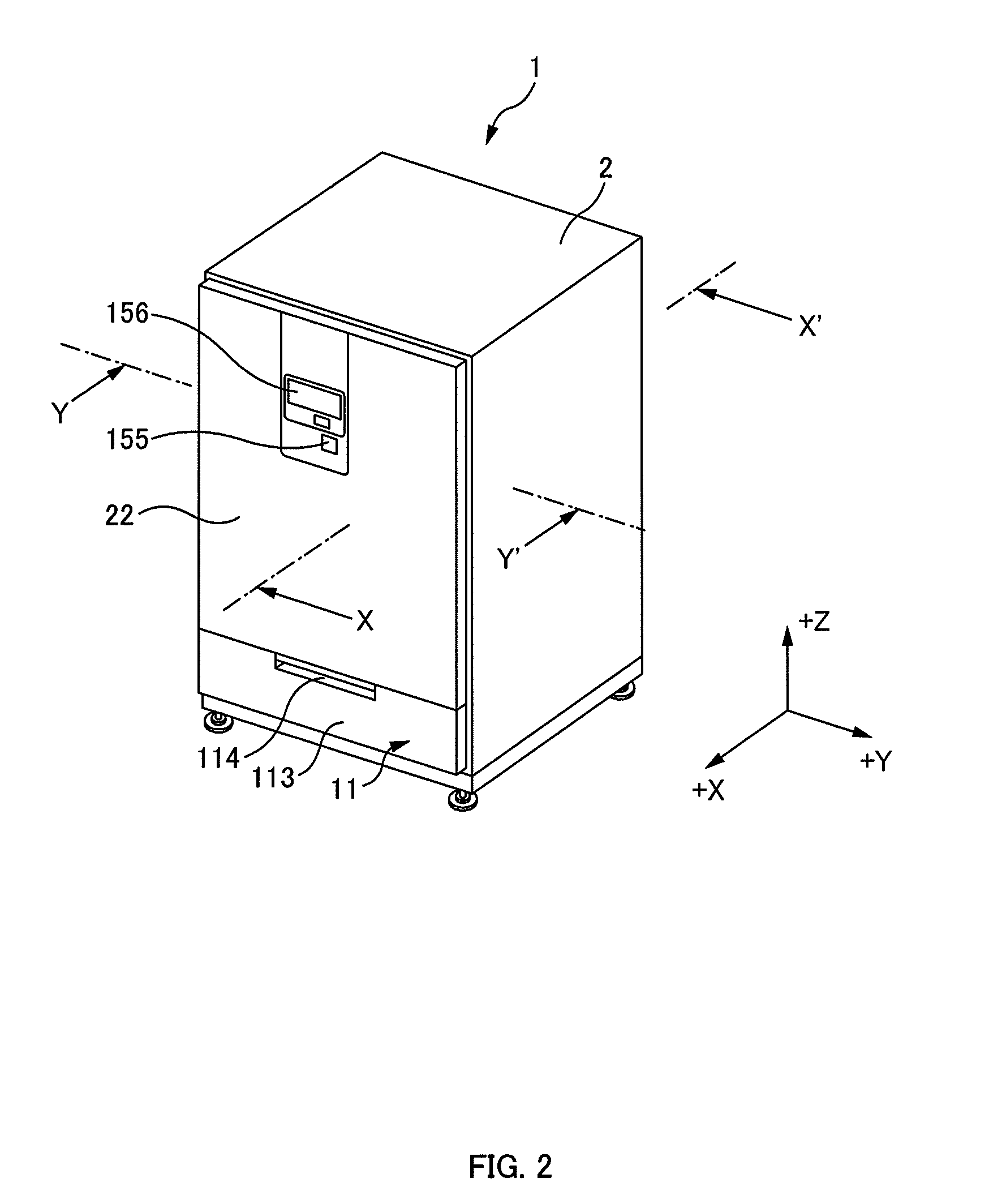
[0029]FIG. 1 is an external perspective view of an incubator 1 as viewed from the front (+X direction). FIG. 2 is an external perspective view of the incubator 1 as viewed from the same direction as in FIG. 1, and depicts the incubator 1 in a state where an outer door 22 and an inner door 32, which will be described later, are closed and a drawer 11, which will be described later, is stored in a storage unit 12, which will be described later, provided in an outer box 2. FIG. 3 is a cross-sectional view of the incubator 1 along a line Y-Y′ of FIG. 2. FIG. 4 is a cross-sectional view of the incubator 1 along a line X-X′ of FIG. 2.

[0030]As illustrated in these drawings, the incubator 1 includes the outer box 2, an inner box 3 provided inside the outer box 2, and a drawer...

second embodiment

[0070]FIG. 9 is a cross-sectional view of the incubator 1 which is to be described as a second embodiment of the present invention. The incubator 1 according to a second embodiment of the present invention differs from the incubator 1 according to a first embodiment of the present invention in a structure inside the inner box 3 and an air circulation path inside the inner box 3, but is the same as the incubator 1 according to a first embodiment of the present invention in other configurations.

[0071]As illustrated in the drawing, the incubator 1 according to a second embodiment of the present invention does not include a configuration corresponding to the case 41 in the incubator 1 according to a first embodiment of the present invention. In the incubator 1 according to a second embodiment of the present invention, a back face board 45 is provided on the back face side (−Y side) of the inner box 3 and is disposed in parallel with the backboard 311 of the inner box 3, extending over t...


PUM

PropertyMeasurementUnit
heightaaaaaaaaaa
humidityaaaaaaaaaa
densityaaaaaaaaaa

Abstract

An incubator comprising: a culture chamber configured to accommodate culture; a dish structure configured to contain a liquid; an ultrasonic vibrator provided in a part of the dish structure, the ultrasonic vibrator configured to atomize the liquid; and a gas-liquid contact structure configured to bring the atomized liquid into contact with air in the chamber to be cultured.

Description

CROSS-REFERENCE TO RELATED APPLICATION[0001]This application claims the benefit of priority to Japanese Patent Application No. 2010-222369, filed Sep. 30, 2010, of which full contents are incorporated herein by reference.BACKGROUND OF THE INVENTION[0002]1. Field of the Invention[0003]The present invention relates to an incubator, and particularly relates to a technology to enable environment control and sterilization control to be performed efficiently for an inside of a culture chamber.[0004]2. Description of the Related Art[0005]A carbon dioxide (CO2) incubator (hereinafter referred to as “incubator”) is known, which includes a means to supply a CO2 gas into a chamber containing culture and a sensor to detect density of the CO2 gas inside a culture chamber (chamber), and controls a supply amount of the CO2 gas according to the density of the CO2 gas.[0006]In the case of changing culture after cultivation thereof using such an incubator, since the culture itself such as a cell and ...

Claims


Application Information

Patent Timeline
Patent Type & Authority Patents(United States)
IPC IPC(8): C12M1/00B06B1/00A61L2/00C12M3/00
CPCC12M37/00C12M41/14
Inventor BUSUJIMA, HIROKITAKAHASHI, YOSHIHIRO
Owner PANASONIC HEALTHCARE HLDG CO LTD
Why Eureka
Try Eureka