Folding bed with a control lever arranged between a cabinet unit and a head part

a control lever and folding bed technology, applied in the direction of beds, beds, couches, etc., can solve the problems of not inconsiderable space, and achieve the effect of reducing space requirements, facilitating extension and erection of folding beds into usage positions, and reliable pivoting of leg units

Inactive Publication Date: 2013-10-29
FERDINAND LUSCH GMBH & CO KG
View PDF11 Cites 10 Cited by
  • Summary
  • Abstract
  • Description
  • Claims
  • Application Information

AI Technical Summary

Benefits of technology

[0032]In a further preferred folding bed a foot part is provided connected pivotably with the head part. The head part and the foot part can be folded together in the respective unused positions such that the back sides of the head part and foot part facing away from the support side are arranged next to each other. Thus with compact dimensions, the folding bed can be stowed neatly in the cabinet unit. It also avoids the lying surfaces lying on each other in the unused position. This could lead to damage or early wear of the lying surface. The corresponding back sides can be positioned adjacent to each other and / or lie on each other for the purposes of better use of the space.
[0033]In the connecting zone between the head part and the foot part, alternatively or additionally at least one leg unit can be provided to support the head part and / or foot part against the floor in the usage position. Here it is suitable if the leg unit is mounted pivotably on the head part and / or foot part in such a manner that the leg unit, on movement of the head part and / or foot part from the unused position into the usage position, is force-pivoted from the unused position into a usage position. The extension and erection of the folding bed into the usage position is thus simplified. It is particularly preferred if the erection of the leg unit is achieved by the change in angle between the head part and the foot part on movement of the folding bed from the unused position into the used position. The reliable pivoting of the leg unit can thus be ensured.

Problems solved by technology

Known folding beds however still have the disadvantage that in the usage position and / or in the unused position, these require a not inconsiderable amount of space.
This is a problem in particular in small rooms in which the benefits of a folding bed are particularly useful.

Method used


Image

  • Folding bed with a control lever arranged between a cabinet unit and a head part
  • Folding bed with a control lever arranged between a cabinet unit and a head part
  • Folding bed with a control lever arranged between a cabinet unit and a head part

Examples


Embodiment Construction

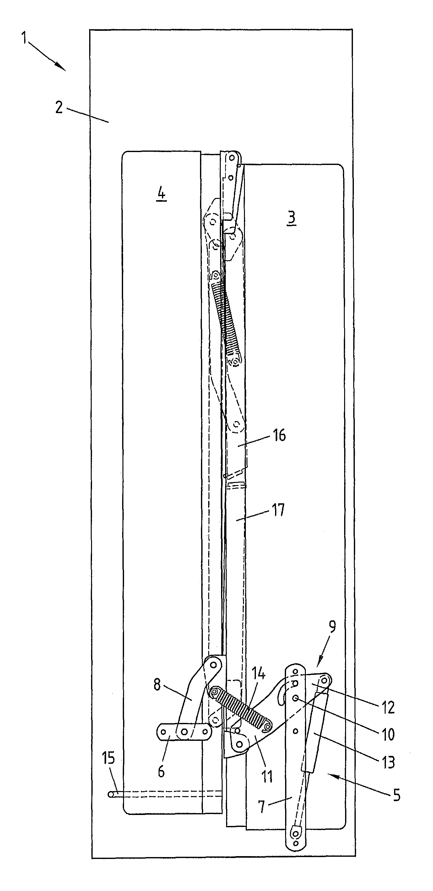
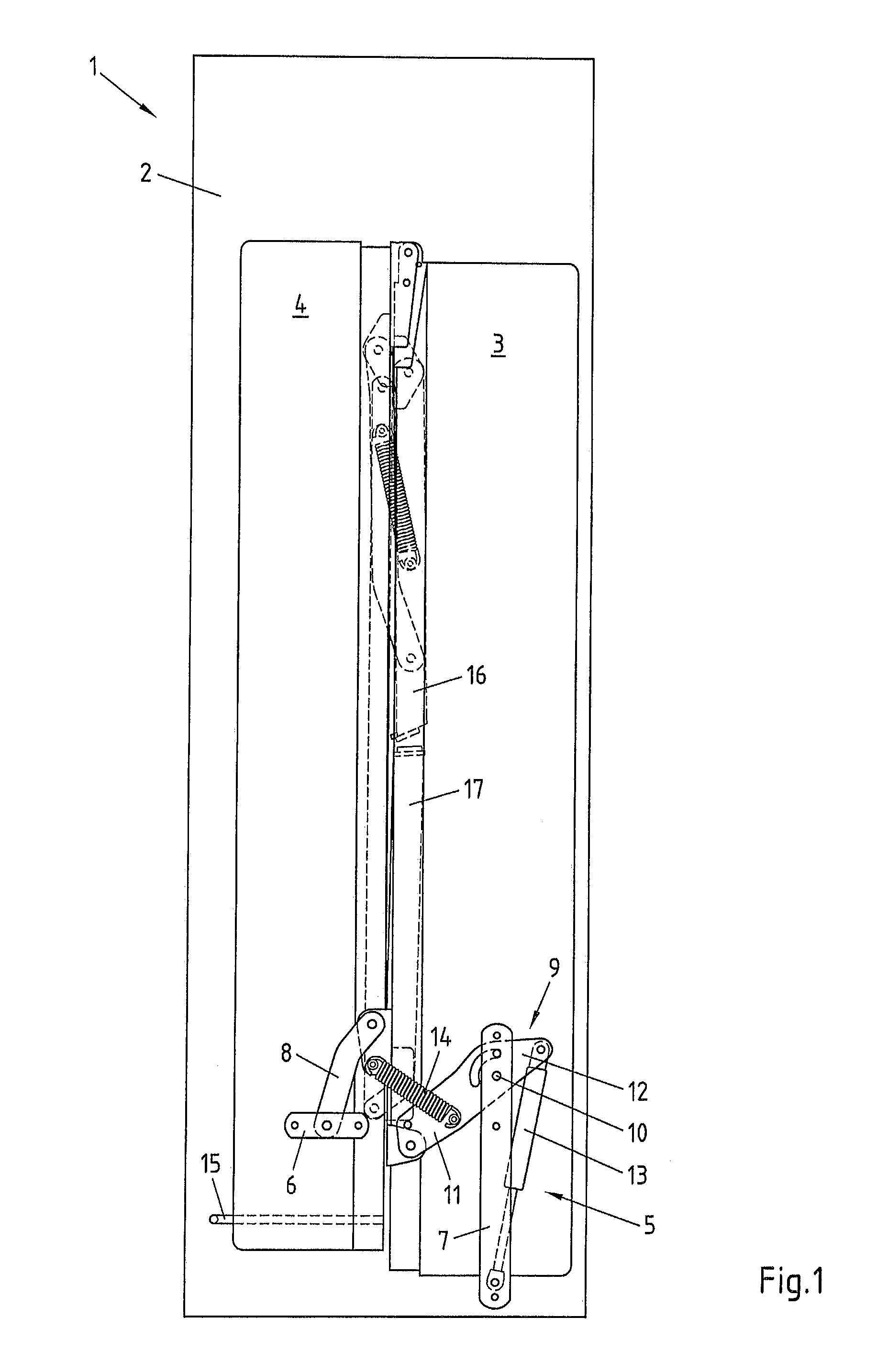
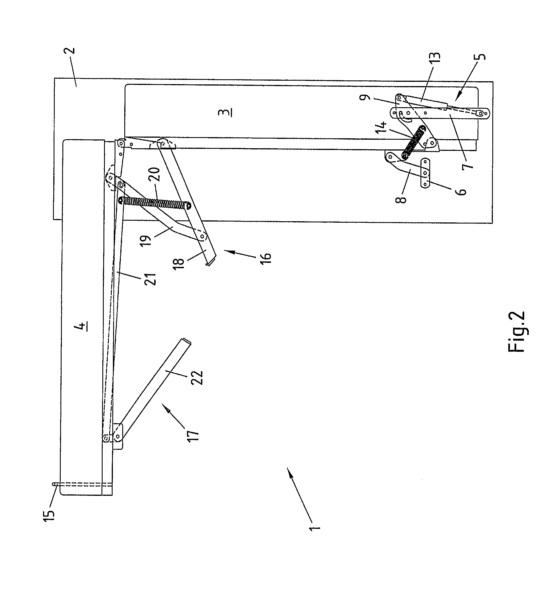
[0042]FIG. 1 shows a folding bed 1 with a cabinet unit 2 which holds a head part 3 and a foot part 4. The head part 3 and foot part 4 are oriented substantially vertically and in an unused position from which the foot part 4 and head part 3 can be pivoted into a usage position in which the two form a common substantially horizontal lying surface.

[0043]The head part 3 is fixed by a fitting 5 to the cabinet unit 2. The fitting 5 has two connecting tabs 6, 7, of which one connecting tab 6 is connected rotatably with a control lever 8. The control lever 8 is also attached rotatably to the head part 3.

[0044]On the other connecting tab 7 provided further in on the cabinet unit 2, a guide lever 9 is mounted rotatably about a rotation axis, wherein the guide lever 9 has a lever arm 11, 12 on both sides of the rotation point 10. One of these lever arms lying in the front of the lever arm 12 pointing to the back of the cabinet unit 2 is connected rotatably with a gas pressure strut 13 which i...


PUM


Abstract

Provided is a folding bed including a cabinet unit and a head part pivotable in relation to the cabinet unit, wherein the head part, in an unused position, is positioned in an approximately vertical orientation in the cabinet unit and in a usage position in an approximately horizontal orientation at least in sections in front of the cabinet unit. The head part can be pivoted from the unused position into the usage position and back. In order to further reduce the space required for the folding bed, the cabinet unit and head part are connected together via a control lever that is held pivotable about a pivot axis on the cabinet unit and a pivot axis on the head part. The control lever is designed such that on movement of the head part from the unused position into the usage position and back, it is pivoted against the cabinet unit.

Description

BACKGROUND OF THE INVENTION[0001]1. Field of the Invention[0002]The invention concerns a folding bed with a cabinet unit and a head part pivotable in relation to the cabinet unit, wherein the head part in an unused position is positioned in an approximately vertical orientation in the cabinet unit and in the usage position is positioned in an approximately horizontal orientation at least in sections in front of the cabinet unit, and wherein the head part can be moved from the unused position into the usage position and back.[0003]2. Description of Related Art[0004]Folding beds of the said type have been known for a long time in various designs. Depending on the orientation of the lying surface to the cabinet unit, these are known as longitudinal and transverse sleeper models. In longitudinal sleeper models, the lying surface can be made of one piece or foldable. Folding lying surfaces usually have at least one head part and one foot part, irrespective of whether or not the lying sur...

Claims


Application Information

Patent Timeline
Patent Type & Authority Patents(United States)
IPC IPC(8): A47C17/52
CPCA47C17/48A47C17/58A47C17/52
Inventor GRONE, MATTHIAS
Owner FERDINAND LUSCH GMBH & CO KG
Why Eureka
Try Eureka