Flight control using actuated variable moment arm

a technology of moment arm and flight control, which is applied in the direction of aircraft transmission means, aircraft stabilisation, aircraft power plants, etc., can solve the problems of limiting the effective range or performance of the aircraft, requiring additional power to overcome such loads, and faster control rates similarly imposing increased power demands. , to achieve the effect of increasing or decreasing loads

Active Publication Date: 2013-10-29
THE BOEING CO
View PDF5 Cites 7 Cited by
  • Summary
  • Abstract
  • Description
  • Claims
  • Application Information

AI Technical Summary

Benefits of technology

[0004]Various embodiments provide a system for actuating a control surface of a vehicle about a pivot point. A bracket having a bellcrank is coupled to the pivot point such that the bracket is rotatable about the pivot point to actuate the surface. A power actuator has a shaft coupled to the bracket at a coupling point on the moment arm such that actuation force applied to the shaft results in a moment produced about the pivot point. For this embodiment, a linear actuator is configured to adjust the location of the coupling point with respect to the pivot point to thereby change the length of the moment arm and subsequently the moment produced about the pivot point as the bracket rotates. By verifying the distance between the pivot point and the coupling point while the surface is in motion, the moments produced about the pivot point can be increased or decreased as desired to counteract increasing or decreasing loads applied by aerodynamic effects occurring along the flight control surface.
[0005]Other embodiments provide a method of actuating a surface that moves about a pivot point from a neutral position. A force is applied to a bracket that is coupled to the surface to thereby rotate the bracket with respect to the pivot point, wherein the force is applied at a coupling point on the bracket. While the surface is moving away from the neutral position, the distance between the coupling point and the pivot point is increased to thereby increase the moment produced about the pivot point by the force. In a further embodiment, the distance between the coupling point and the pivot point can be reduced as the surface returns to the neutral position to thereby reduce the moment produced about the pivot point by the force.

Problems solved by technology

Such designs, however, can be somewhat disadvantageous in that the larger surfaces frequently undergo larger aerodynamic loads than comparatively smaller surfaces, thereby demanding additional power to overcome such loads.
Faster control rates similarly impose increased power demands.
The increased demands for electrical and / or hydraulic power can limit the effective range or performance of the aircraft, and / or can reduce the size of the aircraft payload.

Method used


Image

  • Flight control using actuated variable moment arm
  • Flight control using actuated variable moment arm
  • Flight control using actuated variable moment arm

Examples


Embodiment Construction

[0016]The following detailed description is merely exemplary in nature and is not intended to limit the described embodiments or the application and uses of the described embodiments. Furthermore, there is no intention to be bound by any expressed or implied theory presented in the preceding technical field, background, brief summary or the following detailed description.

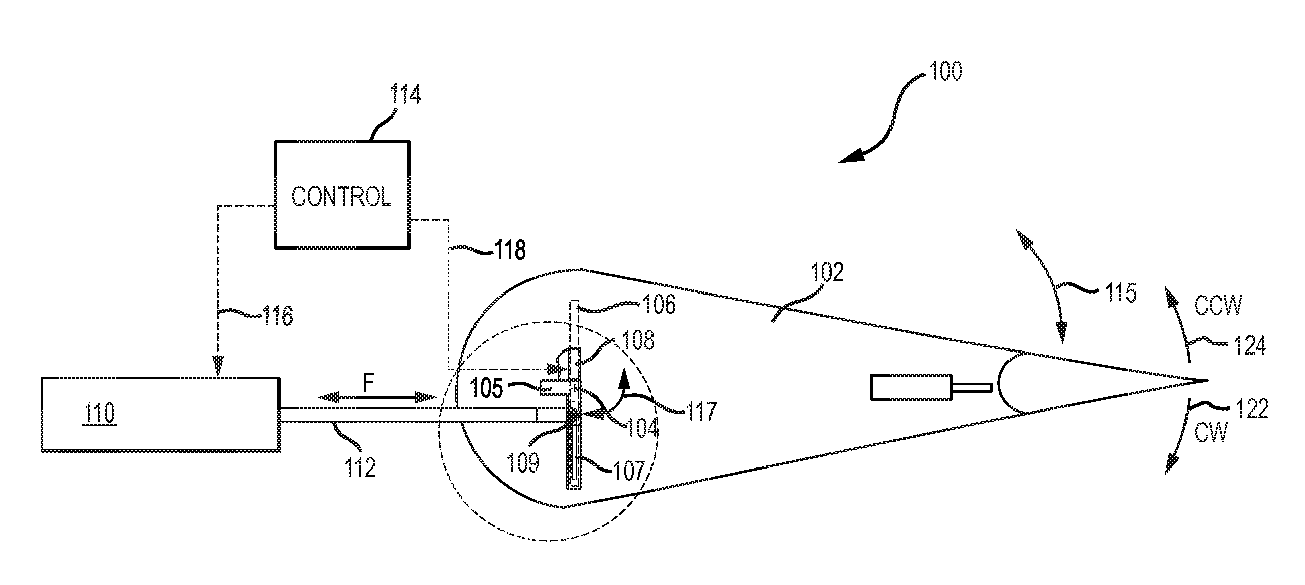
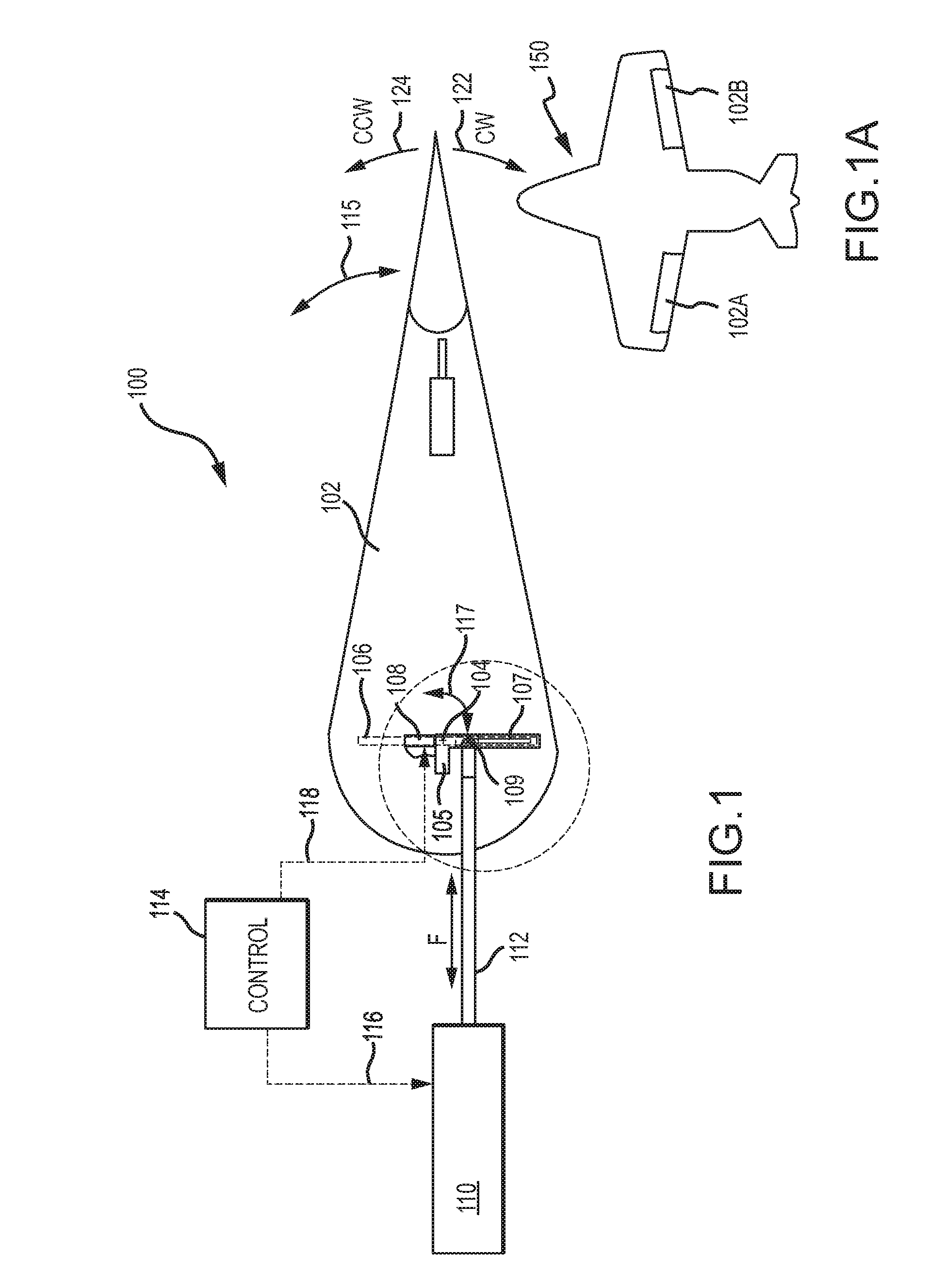
[0017]Power consumption can be greatly reduced by operating one or more control surfaces on the vehicle in a manner that produces variable moments about a pivot point. As a control surface deflects from its neutral position, for example, aerodynamic loads imposed by drag and / or forces acting upon the surface typically increase, which would conventionally require additional force to overcome. Through clever application of mechanical linkages, an actuation system that produces stronger moments as the surface moves can be designed such that the stronger moments are able to reduce the increased aerodynamic effects with ...


PUM


Abstract

Systems and techniques are described for actuating a control surface about a pivot point using variable moments. A bracket having a moment arm is coupled to the pivot point such that the bracket is rotatable about the pivot point to actuate the surface. A power actuator has a shaft coupled to the bracket at a coupling point on the moment arm such that actuation force applied to the shaft results in a moment produced about the pivot point. A linear actuator is configured to adjust the location of the coupling point with respect to the pivot point to thereby changing the moment arm and the moment produced about the pivot point as the bracket rotates. By adjusting the distance between the pivot point and the coupling point, the moments produced about the pivot point can be increased while conserving actuator power.

Description

TECHNICAL FIELD[0001]The embodiments described herein generally relate to flight controls for aircraft. More particularly, the embodiments described herein relate to flight controls that incorporate actuated arms to produce variable moments.BACKGROUND[0002]Conventional aircraft are guided by various flight control surfaces such as rudders, ailerons, flaps, elevators, stabilizers and / or the like. These flight controls are typically moveable on the exterior surface of the aircraft to affect the flow of air in accordance with the principles of aerodynamics, and are widely deployed in various types of manned or unmanned aircraft (including both fixed and rotary-wing aircraft), as well as various missiles, rockets and / or the like.[0003]More recently, aircraft have been designed to be larger and more complex in various ways. The migration to so-called “flying wing” and other tailless aircraft designs, for example, represents a choice to design aircraft with improved performance, but poten...

Claims


Application Information

Patent Timeline
Patent Type & Authority Patents(United States)
IPC IPC(8): B64C5/10
CPCB64C9/02B64C13/24
Inventor SHEAHAN, JR., JAMES J.MORRIS, CHARLES E.ROACH, JEFFREY M.CARTER, HOWARD
Owner THE BOEING CO
Why Eureka
Try Eureka