
Scroll type compressor having an elastic member to suppress noise and reduce variations

a compression compressor and elastic member technology, applied in the direction of machines/engines, rotary/oscillating piston pump components, liquid fuel engines, etc., can solve problems such as rising working costs, and achieve the effect of reducing variations in pressing loads and reducing increases or decreases in pressing loads

Inactive Publication Date: 2013-12-10
MITSUBISHI HEAVY IND LTD
View PDF7 Cites 2 Cited by
  • Summary
  • Abstract
  • Description
  • Claims
  • Application Information

AI Technical Summary

Benefits of technology

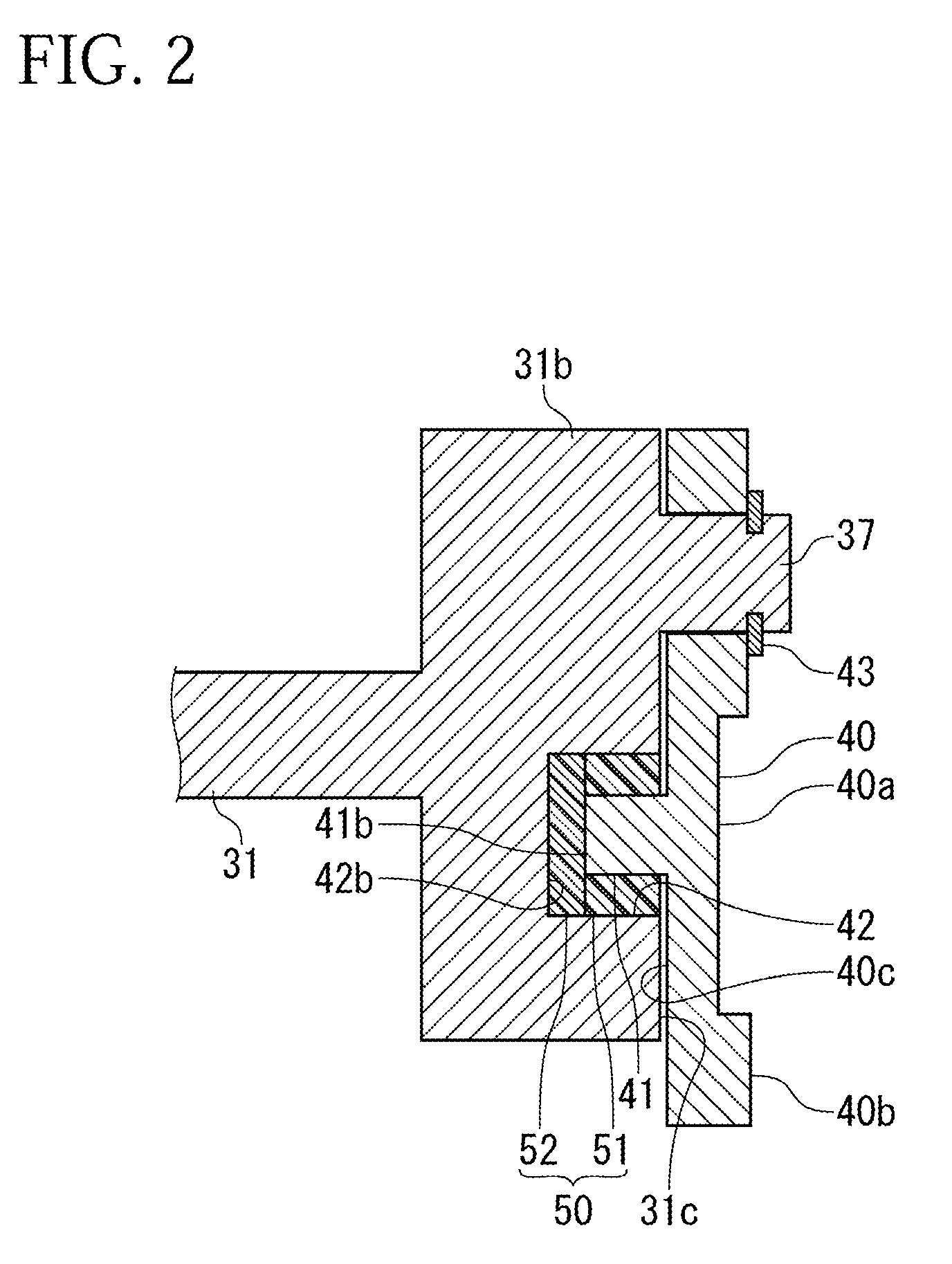
[0026]According to the present invention, the loads under which the rotating scroll is pressed against the fixed scroll are exerted by the first elastic body and the second elastic body and the sealing performance of the compression chamber is secured. At this time, by ensuring that the frictional force exerted by the first elastic body when the convex portion has moved in the direction orthogonal to the axis line in the concave portion, is larger than the repulsive force exerted by the second elastic body, it is possible to reduce an increase or a decrease in the pressing load exerted by the second elastic body when the rotating scroll has been displaced. As a result, even when in the clearance between the concave portion and the convex portion there are errors in the working tolerances of the rotating scroll, the fixed scroll, the main shaft and the like, it is possible to reduce variations in the pressing load exerted by the second elastic body.
[0027]Besides, in a no-load condition (the condition in which the compressor is not operating), it is possible to hold the convex portion in a given position in the concave portion by use of the first elastic body and the second elastic body and it is possible to ensure the arrangement in which the rotating scroll is pressed against the fixed scroll in constant contact relation. As a result of this, it is possible to prevent the rotating scroll, which has been in a noncontact condition, from colliding against the fixed scroll, thereby generating noises at the start of the compressor. Thus, it is possible to make a low-noise compressor.

Problems solved by technology

However, this technique is not desirable because this leads directly to a rise in working cost.

Method used


Image

  • Scroll type compressor having an elastic member to suppress noise and reduce variations
  • Scroll type compressor having an elastic member to suppress noise and reduce variations
  • Scroll type compressor having an elastic member to suppress noise and reduce variations

Examples


Embodiment Construction

[0035]Hereinafter, the present invention will be described in detail on the basis of the embodiment shown in the accompanying drawings.

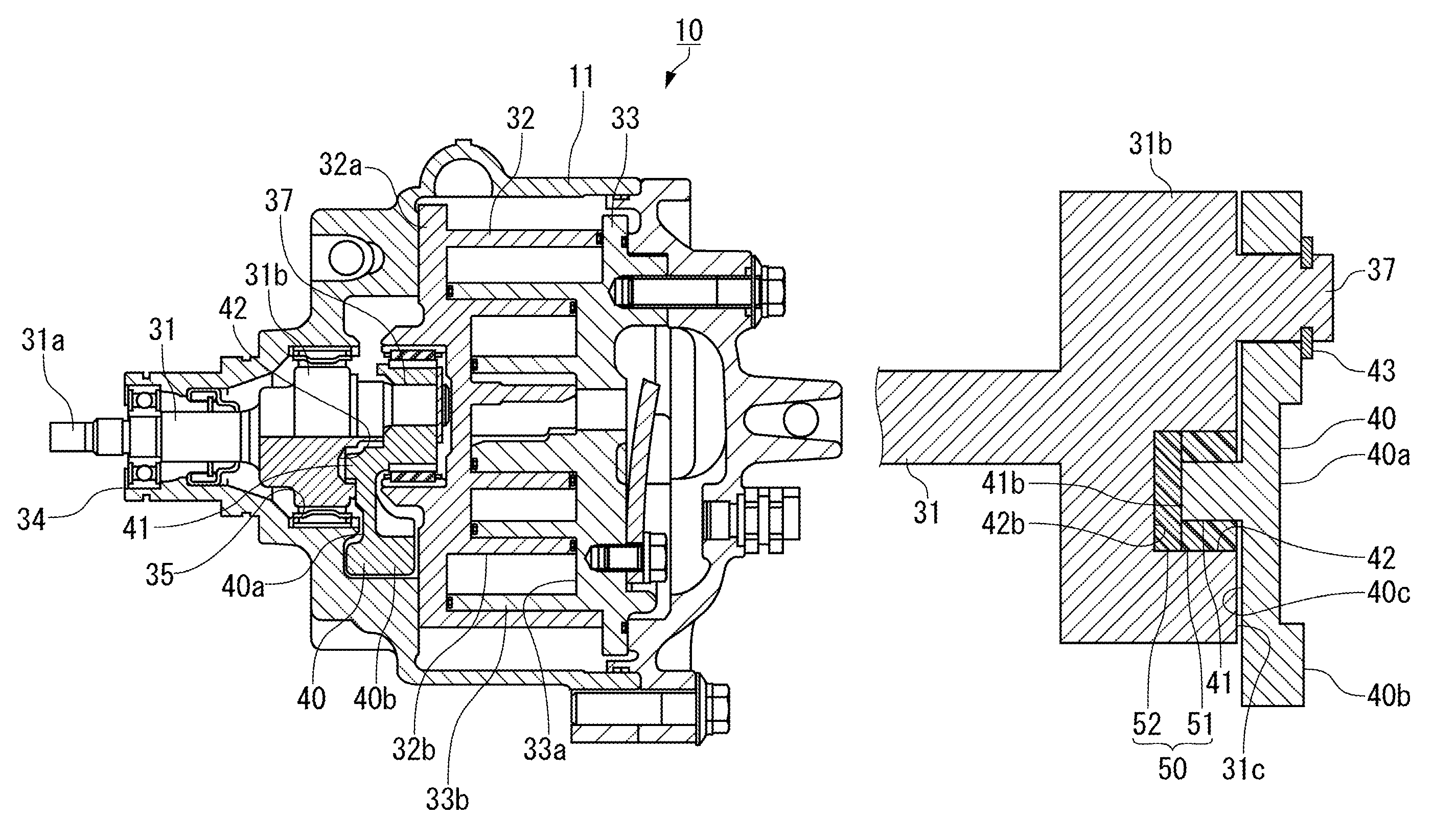
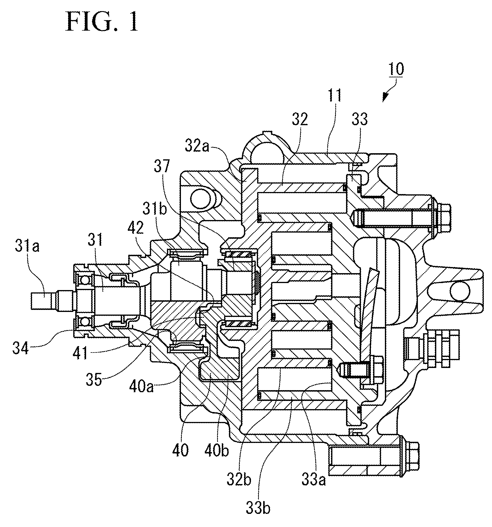
[0036]FIG. 1 is a drawing to show the arrangement of a compressor 10 in this embodiment.

[0037]As shown in FIG. 1, the compressor 10 is of a scroll type and is provided with, within a housing 11, a main shaft 31 and a rotating scroll 32 which rotates along with the main shaft 31, and a fixed scroll 33 fixed to the housing 11.

[0038]In such a compressor 10 like this, a cooling medium is introduced from a cooling medium introduction port formed on one end side of the housing 11 into the housing 11, and the cooling medium is compressed in a compression chamber formed between the rotating scroll 32 and the fixed scroll 33. And the compressed cooling medium is discharged from a cooling medium discharge port formed on the other end side of the housing 11.

[0039]The main shaft 31 is such that both end portions thereof are rotatably supported via bearings 34, 3...


PUM


Abstract

Provided is a scroll type compressor which reduces variations in the pressing load of a rotating scroll on a fixed scroll, reduces the impact at the start of the compressor and suppresses noises, and can provide excellent durability. A peripheral elastic body 51 and a bottom-portion elastic body 52, which is brought into a compressed condition in the axis line direction of the main shaft 31, are interposed between a stopper pin 41 on the rotating scroll side and a concave portion 42 on the main shaft 31 side, whereby working errors of each part are compensated and the rotating scroll is constantly brought into close contact with the fixed scroll to maintain the sealing of the compression chamber.

Description

TECHNICAL FIELD[0001]The present invention relates to a scroll type compressor which constitutes an in-car air conditioner and the like.BACKGROUND ART[0002]A scroll type compressor is provided with a fixed scroll and a rotating scroll, each having a volute-like scroll wall. And the rotating scroll is caused to perform revolving turning motions with respect to the fixed scroll and the volume of a compression chamber formed between the two scroll walls is reduced, whereby the compression of a fluid in the compression chamber is performed.[0003]As shown in FIG. 6, in such a compressor 1, a cooling medium sucked from a suction port into a housing 2 is conducted into a compression chamber formed between a rotating scroll 3B and a fixed scroll 3A. The cooling medium in the compression chamber is compressed by the revolution of the rotating scroll 3B with respect to the fixed scroll 3A and is discharged from a discharge port formed in the housing 2 to the outside.[0004]Here, the rotating s...

Claims


Application Information

Patent Timeline
Patent Type & Authority Patents(United States)
IPC IPC(8): F03C4/00F04C18/00F04C2/00
CPCF04C18/0215F04C29/0021F04C29/06F04C2240/60F04C2270/12
Inventor TAKEUCHI, MAKOTOSUZUKI, TAKAYUKIOHTA, MASAHIROWATANABE, KAZUHIDE
Owner MITSUBISHI HEAVY IND LTD
Learn More