Housing for encasing an object

a technology for encasing objects and objects, applied in the field of encasing objects, can solve the problems of mistreatment of fragile or otherwise breakable objects, affecting the life of objects, and affecting the quality of objects,

Active Publication Date: 2013-10-29
TREEFROG DEV
View PDF280 Cites 66 Cited by
  • Summary
  • Abstract
  • Description
  • Claims
  • Application Information

AI Technical Summary

Benefits of technology

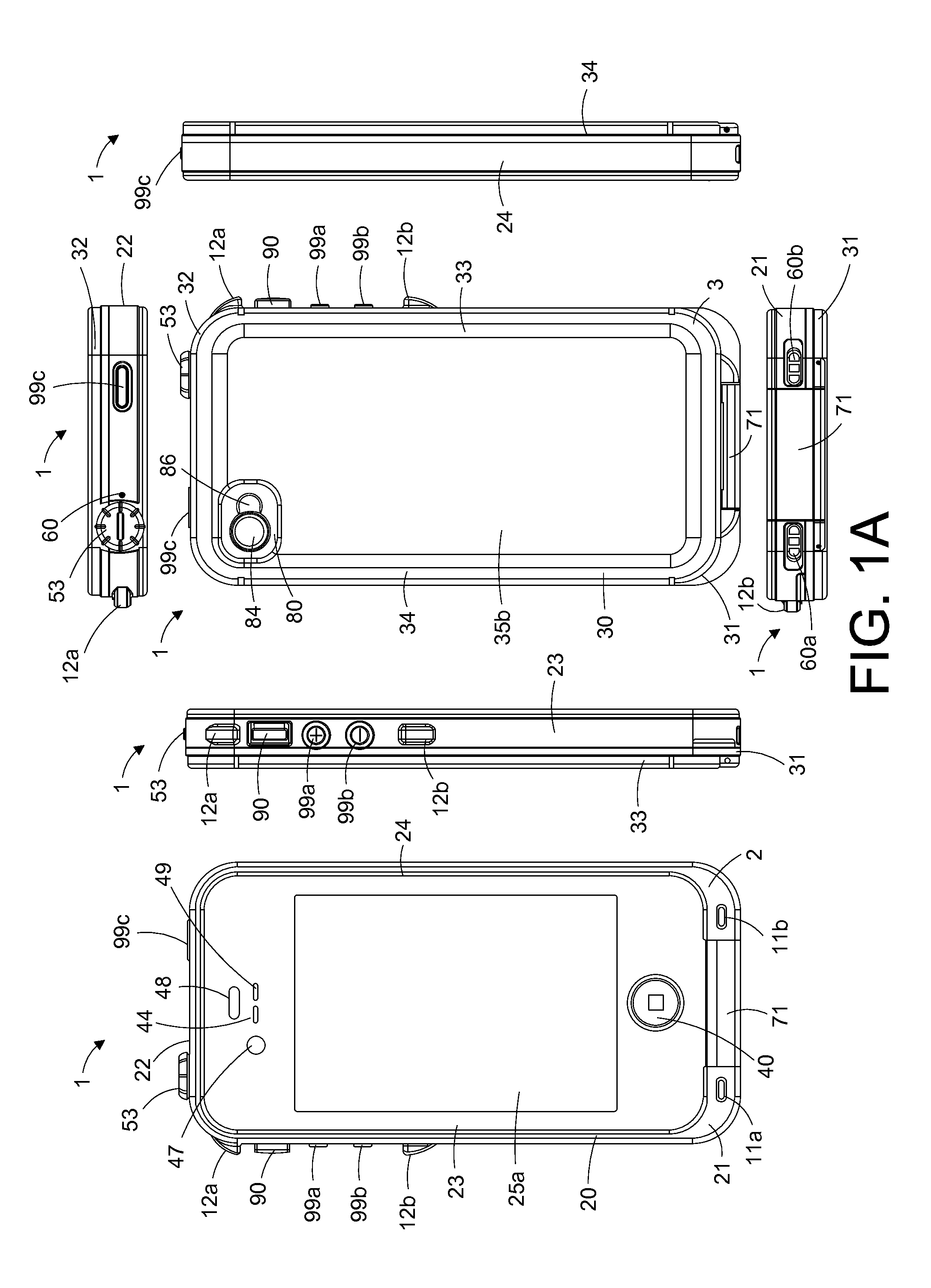
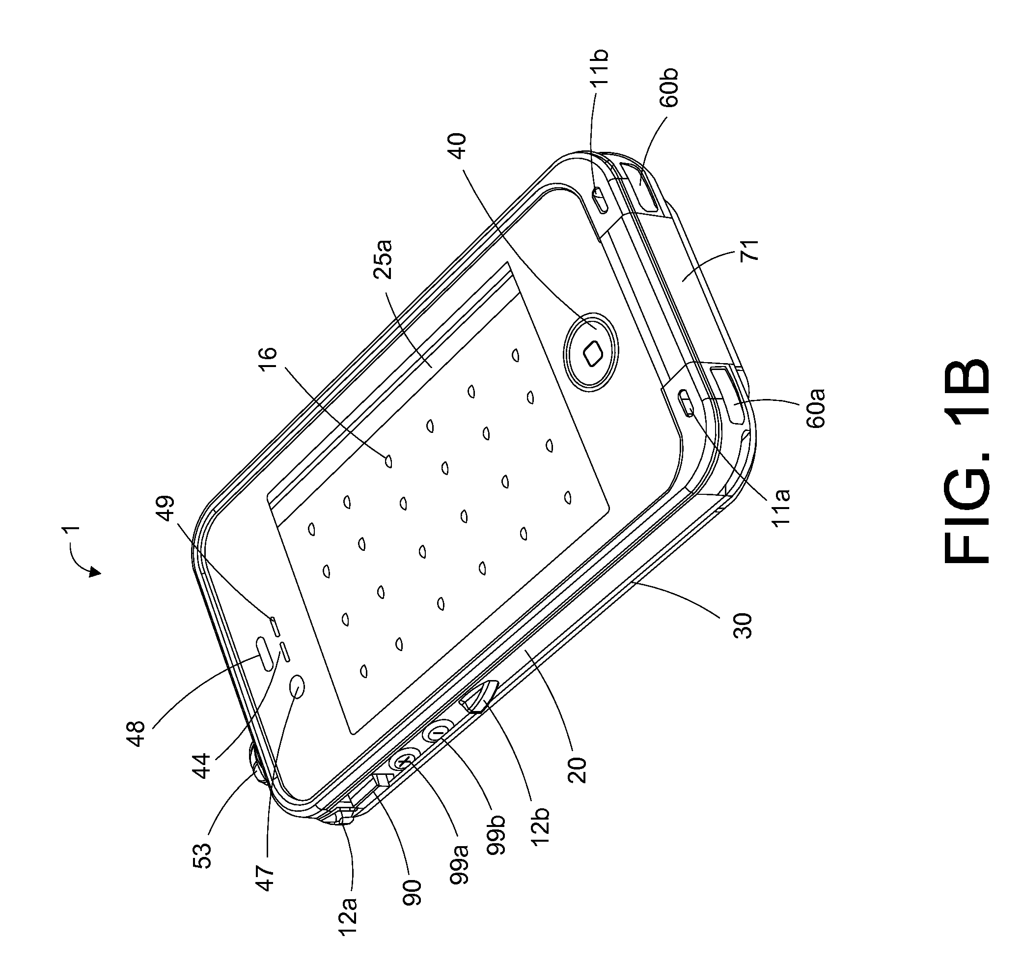
[0020]In another embodiment, for instance, where the housing is intended to house a device with a screen, such as an interactive screen, the front and / or back surfaces of the top and / or bottom member of the housing may each include at least one or more membranes. For instance, the top or bottom member may include a membrane, such as a membrane that is configured for interfacing with an interactive screen, e.g., a touch screen, of an encased device in such a manner that when a user touches the membrane one or more characteristics of that touch are transferred to the touch screen of the underlying device, and in this manner a user is able to manipulate the screen of the encased device.
[0030]In an additional embodiment, along with a perimeter portion and / or a front surface membrane, a bottom member may be provided. The bottom member may be comprised simply of a perimeter portion or may include a bottom surface member that spans from one perimeter portion to the other. The bottom member may include one or more features. For instance, the bottom member may include a lens feature, such as a feature that includes one or more lenses, for instance, a camera and / or video lens and / or a flash lens. The lens feature may additionally include an optical skirt, such as a skirt that surrounds the one or more lenses and prevents the transmission of light there through from one lens region to the other lens region.
[0032]In another instance, the perimeter portion, such as a distal or proximal perimeter end portion, may include one or more acoustic vent features for transmitting and / or channeling sound. For instance, an acoustic vent feature may include a sound channel having an acoustic vent material positioned therein. The acoustic vent material may span the sound channel at an angle from 0 to 180 degrees in a forward or reverse direction. The sound channel may extend from an exterior portion of the perimeter to an interior portion of the perimeter so as to permit the ingress and egress of sound there through, and the acoustic vent material may transect the sound channel, e.g., at an angle with respect to a centerline there through, so as to prevent the ingress (or egress) of water there through.
[0033]In one instance, the perimeter portion, such as one of the opposing side portions, may include a switch feature for engaging a switch mechanism of an encased device. The switch feature may include a switch housing and an actuator having a switch interface. The switch feature may additionally include an axle configured for being coupled to the switch housing and / or the switch interface. The switch feature may be configured such that as the actuator moves, such as rotates about the axle (if included), from a first position to a second position within the switch housing, the switch interface causes the switch to move from a first to a second position, such as from an “on” to an “off” position. In certain embodiments, one or more protective bumper portions may be positioned around the one or more switches or buttons so as to protect them from impact.

Problems solved by technology

Rain, dirt, dust, mud, snow, and water in all of its forms can be damaging to various objects.
Additionally, objects that are fragile or otherwise breakable can be damaged by mistreatment and / or other inappropriate handling, such as by dropping.
While these devices may be portable and handy to use, they suffer from some drawbacks.
For example, they are often expensive and contain fragile electronic components that make them prone to damage due to inclement weather and / or mishandling.

Method used


Image

  • Housing for encasing an object
  • Housing for encasing an object
  • Housing for encasing an object

Examples


Embodiment Construction

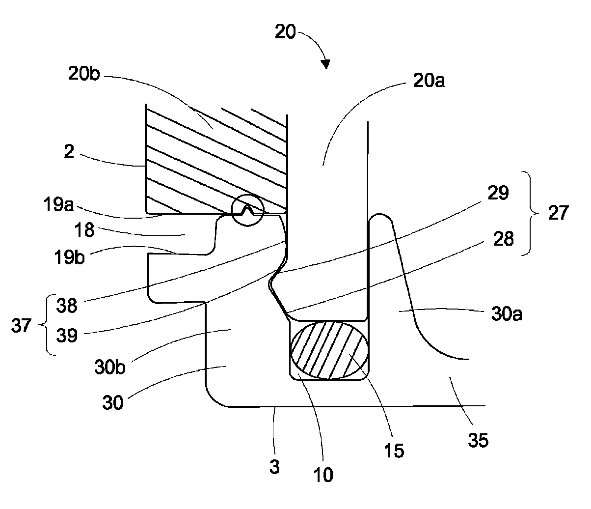
[0064]The subject matter described herein relates generally to a housing for encasing an object. It is to be understood that although the singular “object” is used herein, the term encompasses one or more objects. The object or objects may be any object that is capable of being fit within the housing and / or in need of protecting from one or more adverse environmental conditions, inclement weather, mishandling and / or damage, such as damage from contacting a liquid, such as water, or damage from dropping. The housing may be of any appropriate size and dimension so long as it is capable of housing the object and protecting it, for instance, from adverse environmental conditions and / or rough treatment. The object may be fabricated, e.g., a textile; manufactured; e.g., an electronic or mechanical device; synthesized; naturally occurring; processed; perishable, e.g., a food product; a precious item; and the like. The object may be a single object, like an electronic device, or may be a pl...


PUM


Abstract

This disclosure relates generally to an apparatus and / or system for housing a device. The apparatus includes a housing that is configured such that a device may be fitted within the housing and thereby be protected, such as from shocks and / or liquid. The housing may include top and bottom members that may be removably coupled together so as to form the housing. Each top and bottom member optionally includes front and back surfaces surrounded by a perimeter. The perimeter is defined by proximal and distal ends as well as opposing sides. The top and bottom members may include respective clasping mechanisms that extend along the perimeter of the top and bottom members. The clasping mechanisms are configured for coupling the top and bottom members with one another thereby sealing the housing, for instance, in a shock-proof and / or water tight seal.

Description

CROSS REFERENCE TO RELATED APPLICATIONS[0001]This application is a continuation of U.S. patent application Ser. No. 13 / 272,156, now U.S. Pat. No. 8,342,325, filed Oct. 12, 2011, entitled “Housing For Encasing An Object,” which claims priority from U.S. Provisional Application No. 61 / 392,361, with filing date of Oct. 12, 2010; U.S. Provisional Application No. 61 / 444,085, with filing date of Feb. 17, 2011; and U.S. Provisional Application No. 61 / 471,058, with filing date of Apr. 1, 2011. The disclosures of each of the applications cited in this paragraph are incorporated herein by reference in their entireties.FIELD[0002]This disclosure relates generally to a housing for protecting one or more objects, such as an object in need of protection from the elements, mishandling, and / or other mistreatment. For instance, in one aspect, the disclosure relates to a housing for protecting one or more components of a device or a device itself, such as an electronic device, for example, an electro...

Claims


Application Information

Patent Timeline
Patent Type & Authority Patents(United States)
IPC IPC(8): G06F1/16B65D6/40B65D85/00H04M1/00
CPCG06F1/1626G06F1/1637G06F1/1656H05K5/061H05K5/0217B65D85/00G06F1/1601H05K5/0221A45C13/002G06F1/1613G06F2200/1633A45C11/00A45C2011/002A45C2011/003H05K5/0013G03B17/08G06F2200/1631H04M1/00G06F1/16H05K5/0017H05K5/0004H05K5/06H05K5/069
Inventor RAYNER, GARY
Owner TREEFROG DEV
Why Eureka
Try Eureka