Linear vibration motor having a buffer member

a buffer member and vibration motor technology, applied in the direction of magnetic bodies, dynamo-electric components, dynamo-electric machines, etc., can solve the problems of inability to increase the amount of vibration produced by the vibration motor, restrict the thickness of the terminal,

Inactive Publication Date: 2013-11-05
MPLUS
View PDF16 Cites 73 Cited by
  • Summary
  • Abstract
  • Description
  • Claims
  • Application Information

AI Technical Summary

Problems solved by technology

However, in the case of vertical vibrations, a vertical displacement must be secured for the mass body to move to generate vibrations, resulting in a restriction in the thickness of the terminal.
Also, the reduction in the thickness of the terminal causes a problem in that the amount of vibrations produced by the vibration motor cannot be increased.

Method used


Image

  • Linear vibration motor having a buffer member
  • Linear vibration motor having a buffer member
  • Linear vibration motor having a buffer member

Examples


Embodiment Construction

[0030]Exemplary embodiments of the present invention will now be described in detail with reference to the accompanying drawings. The invention may, however, be embodied in many different forms and should not be construed as being limited to the embodiments set forth herein. Rather, these embodiments are provided so that this disclosure will be thorough and complete, and will fully convey the scope of the invention to those skilled in the art. In the drawings, the shapes and dimensions may be exaggerated for clarity, and the same reference numerals will be used throughout to designate the same or like components.

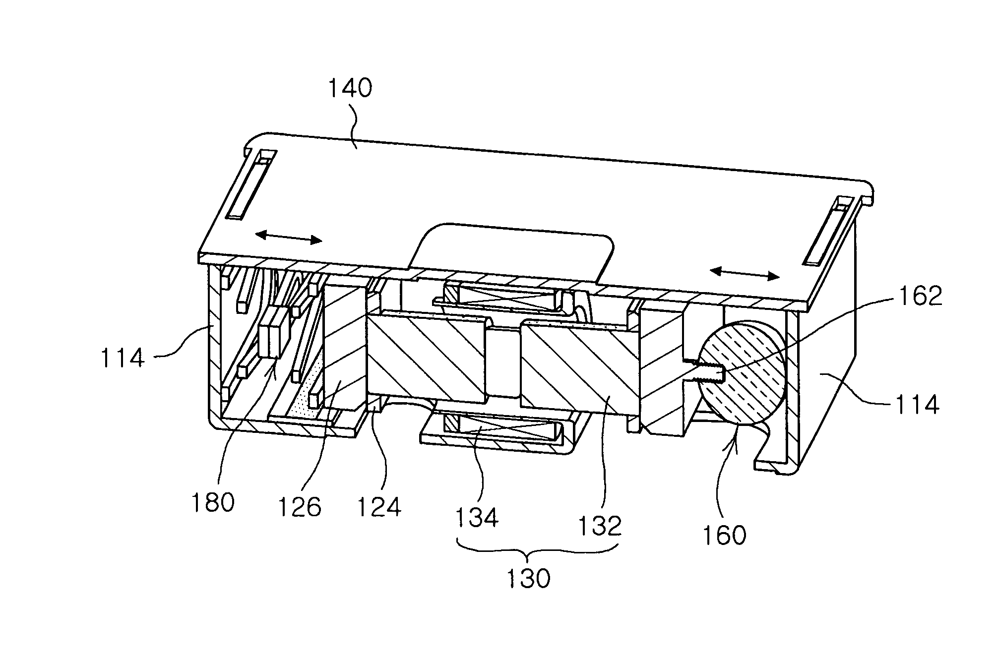
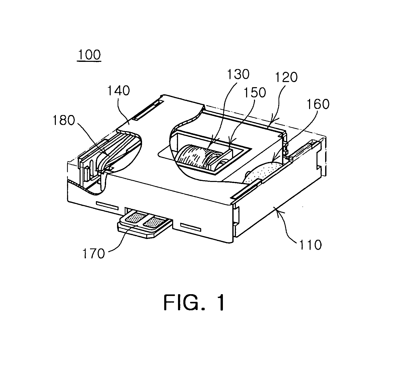
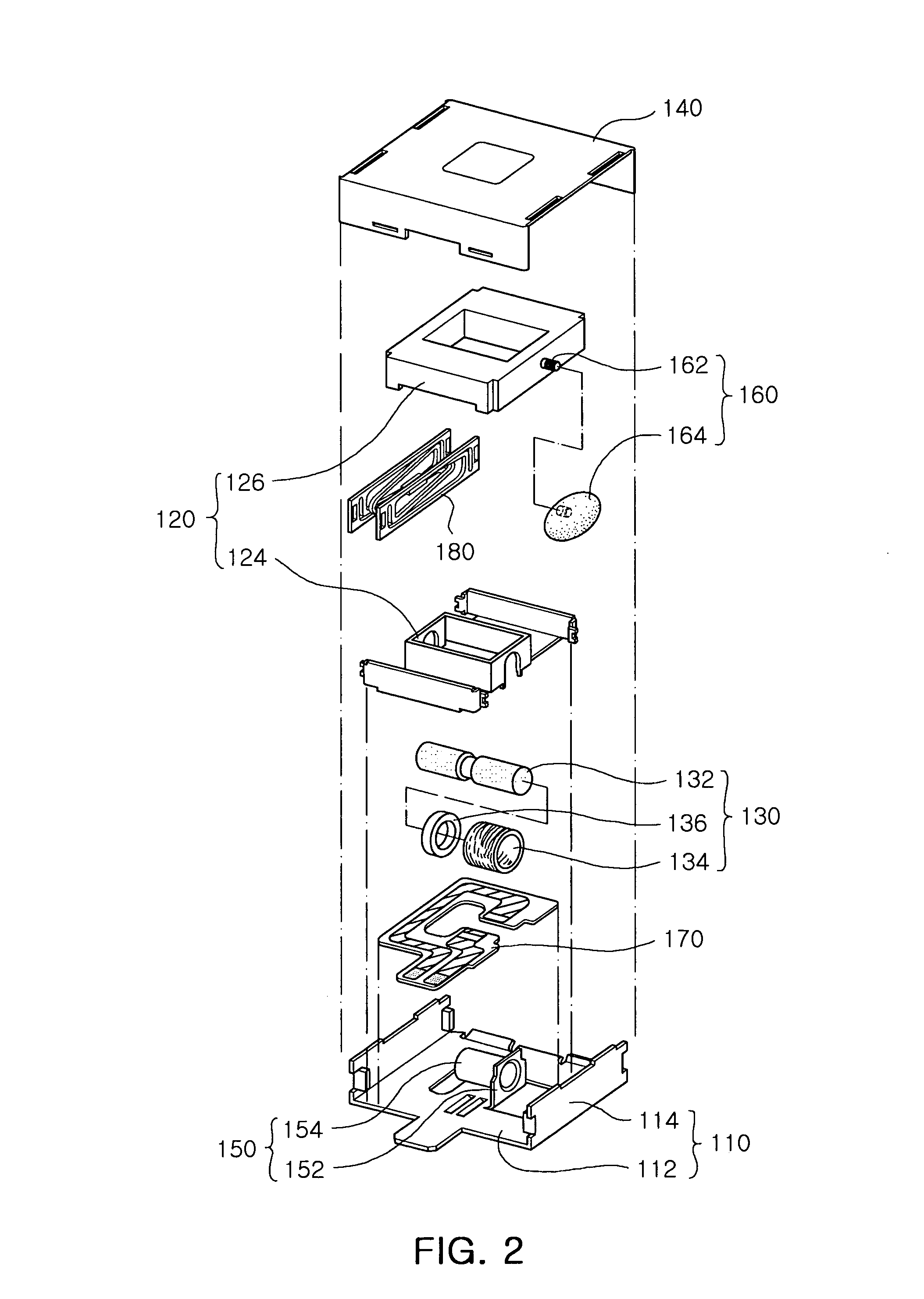
[0031]FIG. 1 is a partially cut-away perspective view of a linear vibration motor according to an exemplary embodiment of the present invention, and FIG. 2 is an exploded perspective view of the linear vibration motor according to an exemplary embodiment of the present invention.

[0032]FIG. 3 is a schematic perspective view showing the interior of the linear vibration motor w...


PUM


Abstract

A linear vibration motor includes: a top cover; a bracket coupled with the top cover to provide an internal space; a vibration unit having a mass body mounted at the internal space and linearly moving in a horizontal direction; an actuator having a magnet fixed to the mass body and a coil installed within a range of a magnetic field of the magnet and generating electromagnetic force to allow the vibration unit to move linearly in a horizontal direction; and a buffer member disposed in a space between the mass body and the bracket and limiting displacement of the vibration unit.

Description

CROSS-REFERENCE TO RELATED APPLICATIONS[0001]This application claims the priority of Korean Patent Application No. 10-2009-0086035 filed on Sep. 11, 2009, in the Korean Intellectual Property Office, the disclosure of which is incorporated herein by reference.BACKGROUND OF THE INVENTION[0002]1. Field of the Invention[0003]The present invention relates to a linear vibration motor and, more particularly, to a linear vibration motor for vibrating a mass body in a horizontal direction within a mobile terminal and having a buffer member for the mass body.[0004]2. Description of the Related Art[0005]A vibration motor is a component for converting electric energy into mechanical vibrations by using the principle of the generation of electromagnetic force. The vibration motor, tending to become smaller and lighter, is employed in a mobile terminal to provide a mute (or silent) incoming call notification function or various vibration functions.[0006]In particular, as mobile terminals have bee...

Claims


Application Information

Patent Timeline
Patent Type & Authority Patents(United States)
IPC IPC(8): H02K33/02H02K35/02H02K33/00H02K35/00
CPCH02K33/18H01F7/1615H01H3/3042H02K33/04
Inventor LEE, JEE SUNGLEE, KWANG HYUNG
Owner MPLUS
Why Eureka
Try Eureka