Image forming apparatus featuring control voltages applied to magnetic particle carrying members

a technology of magnetic particle carrying member and control voltage, which is applied in the direction of electrographic process apparatus, instruments, corona discharge, etc., can solve the problems of unfavorable image forming apparatuses that employ injection charging methods, unlikely to yield images of lower quality, and potential level to which the image bearing member is charged, etc., to achieve efficient charging

Inactive Publication Date: 2013-11-05
CANON KK
View PDF8 Cites 1 Cited by
  • Summary
  • Abstract
  • Description
  • Claims
  • Application Information

AI Technical Summary

Benefits of technology

[0008]Thus, the primary object of the present invention is to provide an image forming apparatus which employs multiple magnetic particle bearing members, and yet, efficiently minimizes the amount of the deviation in the potential level to which the surface of its image bearing member is charged, by optimally controlling the voltage to be applied to the magnetic particle bearing members.
[0010]The present invention can provide an image forming apparatus which has multiple magnetic particle bearing members, and uniformly and efficiently charges its magnetic particle bearing member by properly controlling the voltage to be applied to the magnetic particle bearing members.

Problems solved by technology

These charging methods, however, result in the formation of unwanted products attributable to electrical discharge.
Since the charging methods of the injection type do not use electrical discharge, they do not produce substances attributable to electrical discharge.
Thus, image forming apparatuses which employ a charging method of the injection type are unlikely to yield images of lower quality, the low quality of which is attributable to the products which result from the electrical discharge:
However, image forming apparatuses which employ any of the charging methods of the injection type have the following problems.
However, it still suffers from the problem that the potential level to which its image bearing member is charged is affected by the most downstream magnetic particle bearing member in terms of the moving direction of the peripheral surface of the image bearing member.
There is also another problem.
However, with the use of the above-described voltage controlling method, it is rather difficult to reliably minimize the amount of the deviation in the potential level to which the peripheral surface of the image bearing member of the apparatus is charged.
This method however cannot be said to be effective, because each time the voltage to be applied to the magnetic particle bearing members are varied in value, the image forming apparatus has to be idled.
Moreover, it is possible that while the voltage to be applied to the magnetic particle bearing members is changed in steps in value, an improper voltage is applied.
If an improper voltage is applied to the magnetic particle bearing members, it is possible that the magnetic particles adhere to the surface of the image bearing member and / or the surface of the image bearing member is damaged by an excessive amount of voltage.

Method used


Image

  • Image forming apparatus featuring control voltages applied to magnetic particle carrying members
  • Image forming apparatus featuring control voltages applied to magnetic particle carrying members
  • Image forming apparatus featuring control voltages applied to magnetic particle carrying members

Examples


embodiment 1

1-1: General Structure of Image Forming Apparatus

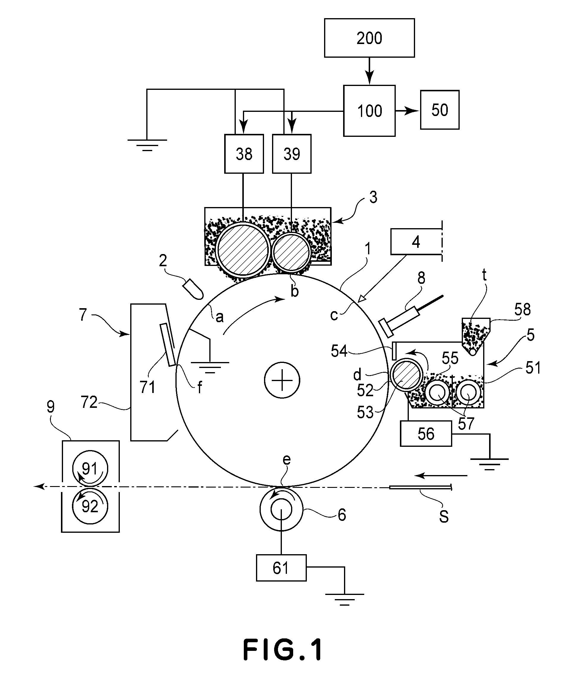
[0026]First, referring to FIG. 1, the general structure of the image forming apparatus in the first preferred embodiment of the present invention is described. The image forming apparatus in this embodiment is an electrophotographic image forming apparatus. It employs a magnetic brush as a charging means, develops an electrostatic latent image in reverse, and is of the transfer type. As examples of an image forming apparatus similar to the image forming apparatus in this embodiment, there are electrophotographic copying machines, electrophotographic printers, facsimileing machines, word processors, apparatuses capable of performing two or more functions of the preceding apparatuses, etc.

[0027]The image forming apparatus in this embodiment has an electrophotographic photosensitive member 1 (which hereafter will be referred to simply as photosensitive drum 1), which is a rotatable image bearing member. The photosensitive drum 1 is in th...

embodiment 2

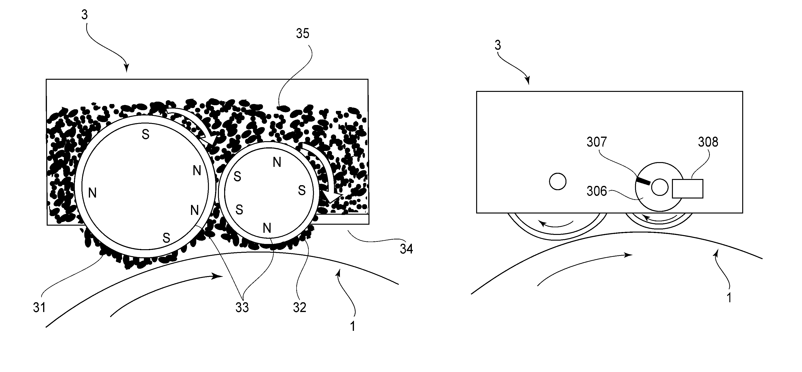
[0099]As described above, all that is necessary to reduce the amount of the deviation in the potential level to which the peripheral surface of the photosensitive drum 1 is charged, is to control the charging apparatus in real time to set the upstream and downstream DC voltages to the values at which the phase difference reverses. In the first embodiment, therefore, the charge voltage to be applied to the upstream and downstream charging sleeves 31 and 32, one for one, were controlled in their DC components.

[0100]However, the means for altering a charging apparatus in performance does not need to be limited to the means which controls the charge voltages in their DC component. For example, the voltages to be applied to the upstream and downstream charging sleeves 31 and 32, one for one, may be controlled in their AC component. In this embodiment, therefore, the charging apparatus is controlled in the AC component (upstream AC) to be applied to the upstream charging sleeve 31, and th...


PUM


Abstract

An image forming apparatus includes a rotatable drum, a charging section for charging the drum, a latent image forming section, a potential detector, a phase detector, and a controller. The charging section includes a first carrying member and a second carrying member for carrying electroconductive magnetic particles. The second carrying member is disposed downstream of said first carrying member. The latent image forming section forms a latent image on the drum, and is disposed downstream of the charging section. The potential detector detects a surface potential of the drum, and is disposed downstream of the charging section. The phase detector detects information relating to a rotational phase of the second carrying member. The controller controls voltages applied to the first carrying member and to the second carrying member, on the basis of a result of detection by the potential detector and a result of detection by the phase detector.

Description

FIELD OF THE INVENTION AND RELATED ART[0001]The present invention relates to an image forming apparatus which employs one of electrophotographic image forming methods.[0002]Conventional image forming apparatuses which employ an electrophotographic image forming method have a charging means for uniformly charging the peripheral surface of an image bearing member. As for the changing method employed by the charging means, a charging method of the corona type, a charging method which uses a roller, etc., have been known. A charging method of the corona type is such a charging method that utilizes electrical discharge. These charging methods, however, result in the formation of unwanted products attributable to electrical discharge. Thus, it is possible that electrophotographic image forming apparatuses which employ any of the charging methods of the above-mentioned types sometimes yield images of lower quality. On the other hand, there are image forming methods which do not rely on ele...

Claims


Application Information

Patent Timeline
Patent Type & Authority Patents(United States)
IPC IPC(8): G03G15/02
CPCG03G15/0241G03G15/0266G03G15/5037G03G15/5033G03G2215/022
Inventor MATSUMOTO, RYOTAHONG, YUKWIHORITA, SHINGOHASHIMOTO, KOICHI
Owner CANON KK
Why Eureka
Try Eureka