Table circulation guide device

a technology for guiding devices and tables, which is applied in the direction of mechanical equipment, transportation and packaging, railway components, etc., can solve the problems of affecting the drive apparatus, the sliding device cannot bear large loads, and the large load cannot be carried, so as to improve the accuracy of control, and reduce the number of rails.

Active Publication Date: 2019-07-16
NIPPON THOMPSON
View PDF22 Cites 6 Cited by
  • Summary
  • Abstract
  • Description
  • Claims
  • Application Information

AI Technical Summary

Benefits of technology

[0030]Since the table circulation guide device according to the present invention is configured as described above, an endless circulation circuit is composed of at least a pair of straight track rails and curved track rails disposed adjacent to the opposite end portions of the straight track rails, and the table can circulate and move along the endless circulation circuit. Specifically, when the table travels in working areas on the straight track rails, the table can travel along the straight track rails via at least a pair of sliders traveling on the straight track rails, respectively, and when the table travels in non-working areas on the curved track rails, the table can travel along the curved track rails via carriages attached to the table. As described above, the table circulation guide device can circulate and move the table, to which the sliders and the carriages are attached, along the circuit whose straight portions are formed by the straight rails and whose curved portions are formed by the curved rails, whereby an object, such as a workpiece, a member, equipment, etc., mounted on the table is continuously moved along the circuit.
[0031]In addition, the table circulation guide device eliminates the necessity of performing a high degree of accuracy control for the table having the sliders and the carriages attached thereto, and the circuit composed of the straight rails and the curved rails, large load can be applied to the table, and stable and smooth travel of the table is enabled. In order to minimize the number of rails of the circuit, the straight portions of the circuit where various types of operations are performed are each formed by a pair of straight track rails, and the curved portions of the circuit are each formed by a single curved track rail for circulating and guiding the table. Therefore, the apparatus can be made simple, and the table on which the object is mounted can be continuously circulated along the circuit. The table circulation guide device is configured such that, in each of the straight portions where various types of operations are performed, the table is guided y a pair of straight track rails. Therefore, the load which can be imposed on the table can be increased. In addition, at opposite end portions of the table in the widthwise direction thereof, straight guide rails are disposed as straight track rails such that they are parallel to each other; i.e., are parallel to the longitudinal direction, and the table travels on the straight track rails. Therefore, the amount of deviation of the table can be minimized, and the load imposed on the table can be supported reliably and stably, whereby various types of operations (e.g., machining such as cutting performed on a workpiece, assembly operation, etc.) on an object mounted on the table can be performed reliably and accurately.

Problems solved by technology

Therefore, the slider cannot bear large load.
H11-208859 have a problem in that since an object is moved in a state in which the object is guided by rollers only, large load cannot be borne, unlike the case where the object is guided by a linear guide.
Also, if an unbalanced load is imposed on the table, an unfavorable state, such as generation of large resistance, impact, noise, etc., occurs in a boundary region where the table moves to the straight track rails on the inner and outer sides of the circuit from the curved track rail or the curved guide rails simultaneously.
Also, the unbalanced load imposed on the table may adversely affects the drive apparatus.

Method used


Image

  • Table circulation guide device
  • Table circulation guide device
  • Table circulation guide device

Examples


first embodiment

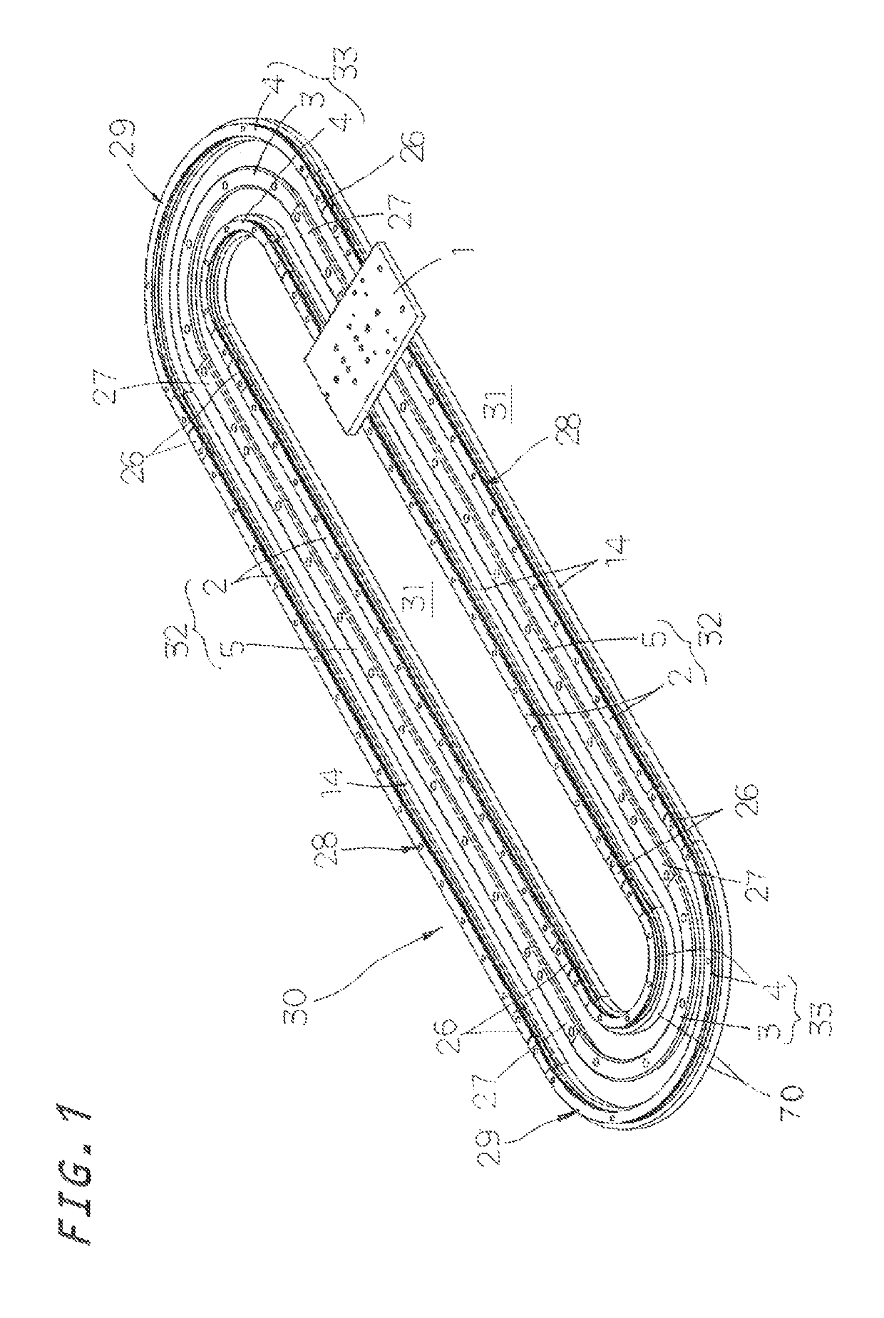
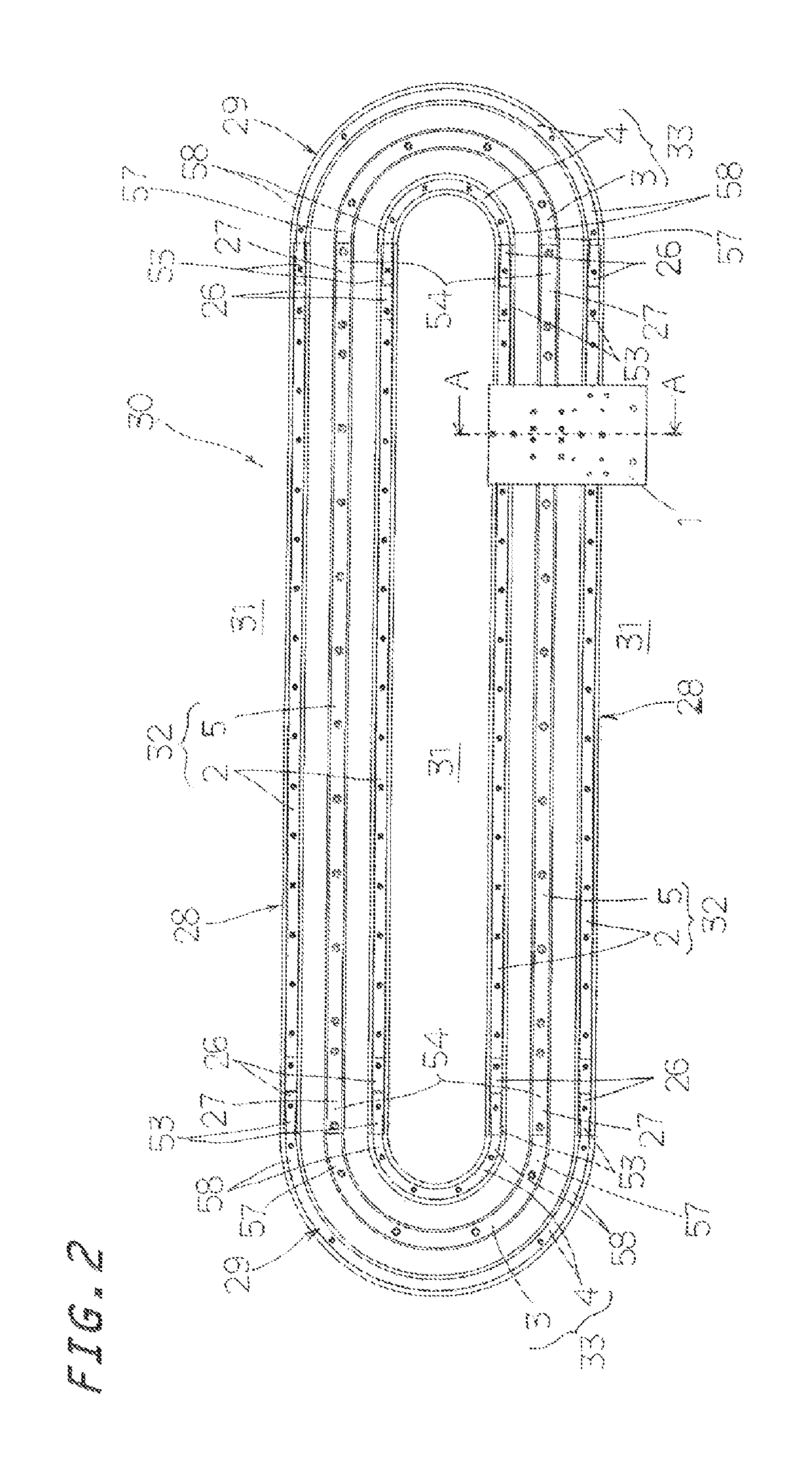
[0065]First, the table circulation guide device according to the present invention will be described with reference to FIGS. 1 to 12. This table circulation guide device can drive a table 1 through use of a drive means such as a linear-motor-type drive means or a belt-drive-type drive means. The table circulation guide device is composed of a bed 31, a circuit 30 on the bed 31, and the table 1 which circulates and moves while being supported by the circuit 30. The circuit 30 is composed of a plurality of straight rails 2 and 5 (which will be collectively referred to as the “straight rails 32”) fixedly disposed in linear motion guide regions which are working areas 28 and a plurality of curved rails 3 and 4 (which will be collectively referred to as the “curved rails 33”) fixedly disposed in curved motion guide regions which are non-working areas. The straight rails 32 include at least two pairs of straight track rails 2 which are parallel to each other, are spaced from each other, a...

fifth embodiment

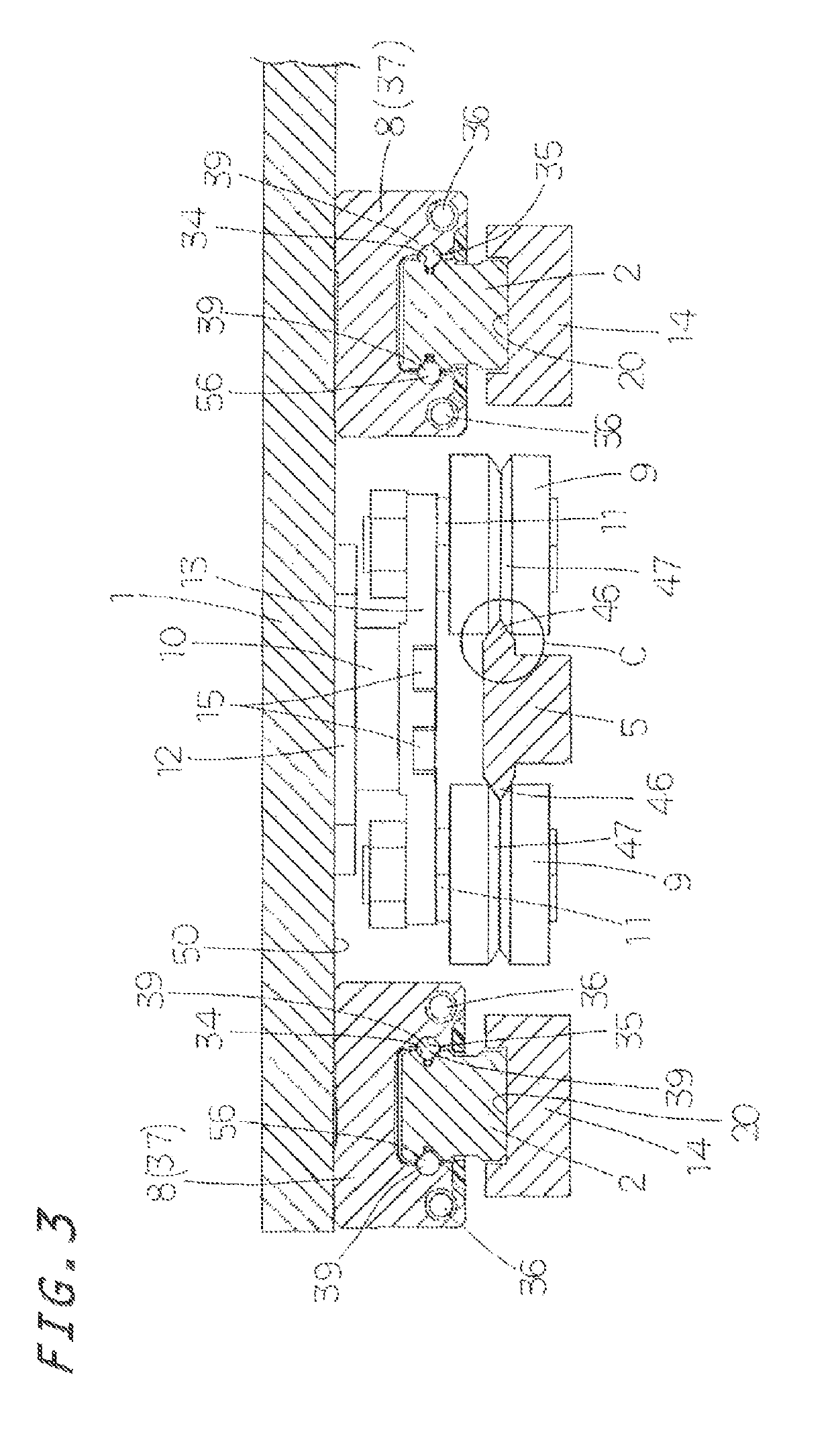
[0078]In the fifth embodiment, a load mounted on each table 1 is located on the outer side of the circuit 30. In consideration of the unbalanced load imposed on the table 1, the table 1 has two sliders 8 which travel on the straight track rails 2 on the outer side of the circuit 30 and one slider 8 which travels on the straight track rails 2 on the inner side of the circuit 30. This configuration allows the table 1 to travel stably irrespective of the unbalanced load imposed on the table 1. The various types of rails which constitute the circuit 30 include two pairs of straight track rails 2 extending straight on the bed 31, straight guide rails 5 each disposed between each pair of straight track rails 2, curved guide rails 4 connected to the opposite end faces of the straight track rails 2 on the inner side of the circuit 30, and curved track rail 3 connected to the opposite end faces of the straight guide rails 5.

[0079]In particular, the fifth embodiment is characterized in that t...


PUM


Abstract

This table circulation guide device includes sliders and carriage attached to a table. In a working area, the table is guided by the sliders straddling straight track rails. In a non-working area, the table is guided by the carriages traveling on a curved track rail. An endless circulation circuit is formed by the straight track rails and the curved track rail. In the working area of the circuit, the table travels via the sliders straddling the straight track rails. In the non-working area of the circuit, the table travels via the carriages located between the sliders.

Description

FIELD OF THE INVENTION[0001]The present invention relates to a table circulation guide device for a table which has sliders and carriages and which is circulated and guided along a circuit formed by straight rails and curved rails.BACKGROUND OF THE INVENTION[0002]Conventionally, a table circulation guide device has been used for a table on which an object such as a workpiece, equipment, etc., is mounted and which is circulated and moved along a circuit. In a working area of a straight guide passage in the middle of the circuit, operations such as machining and assembling work are performed on the object. The circuit is composed of straight guide passages and curved guide passages. In general, the straight guide passages are working areas, and the curved guide passages are non-working areas.[0003]Japanese Patent Application Laid-Open No. 2013-176214 discloses a linear transportation device which moves an object back and forth using a linear motor. The linear transportation device inc...

Claims


Application Information

Patent Timeline
Patent Type & Authority Patents(United States)
IPC IPC(8): B61B13/00B65G39/00B65G35/06
CPCB65G35/06B65G54/02F16C29/045F16C2326/58
Inventor NARA, TSUGUYOSHIMATSUI, MASASHISATO, DAISUKE
Owner NIPPON THOMPSON
Why Eureka
Try Eureka