Image forming apparatus
a technology of image forming apparatus and charging method, which is applied in the direction of electrographic process apparatus, instruments, corona discharge, etc., can solve the problems of unfavorable image forming of unwanted products attributable to electrical discharge, affecting the potential level to which the image bearing member is charged, and image forming apparatuses employing injection-type charging methods are unlikely to yield images of lower quality. , to achieve the effect of efficient charging
- Summary
- Abstract
- Description
- Claims
- Application Information
AI Technical Summary
Benefits of technology
Problems solved by technology
Method used
Image
Examples
embodiment 1
1-1: General Structure of Image Forming Apparatus
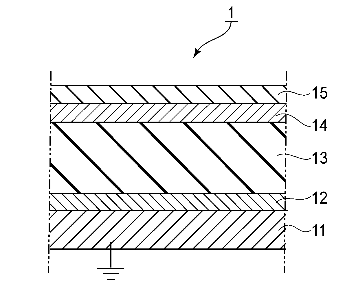
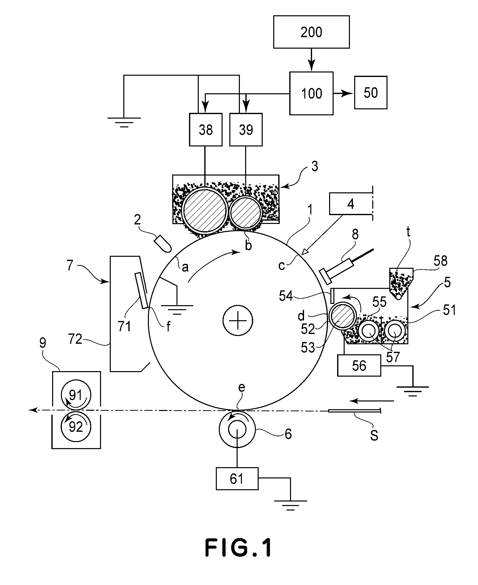
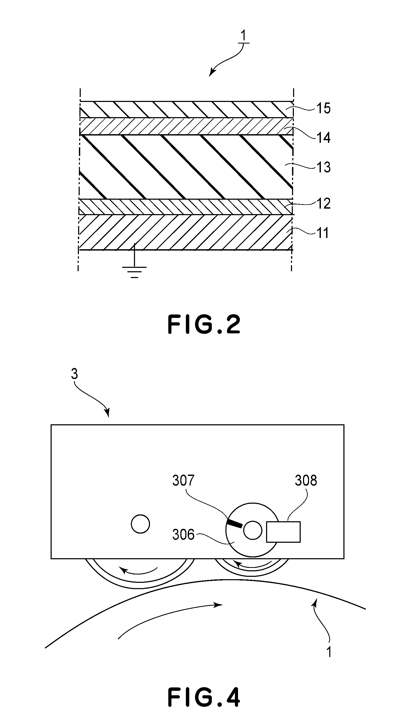
[0026]First, referring to FIG. 1, the general structure of the image forming apparatus in the first preferred embodiment of the present invention is described. The image forming apparatus in this embodiment is an electrophotographic image forming apparatus. It employs a magnetic brush as a charging means, develops an electrostatic latent image in reverse, and is of the transfer type. As examples of an image forming apparatus similar to the image forming apparatus in this embodiment, there are electrophotographic copying machines, electrophotographic printers, facsimileing machines, word processors, apparatuses capable of performing two or more functions of the preceding apparatuses, etc.
[0027]The image forming apparatus in this embodiment has an electrophotographic photosensitive member 1 (which hereafter will be referred to simply as photosensitive drum 1), which is a rotatable image bearing member. The photosensitive drum 1 is in th...
embodiment 2
[0099]As described above, all that is necessary to reduce the amount of the deviation in the potential level to which the peripheral surface of the photosensitive drum 1 is charged, is to control the charging apparatus in real time to set the upstream and downstream DC voltages to the values at which the phase difference reverses. In the first embodiment, therefore, the charge voltage to be applied to the upstream and downstream charging sleeves 31 and 32, one for one, were controlled in their DC components.
[0100]However, the means for altering a charging apparatus in performance does not need to be limited to the means which controls the charge voltages in their DC component. For example, the voltages to be applied to the upstream and downstream charging sleeves 31 and 32, one for one, may be controlled in their AC component. In this embodiment, therefore, the charging apparatus is controlled in the AC component (upstream AC) to be applied to the upstream charging sleeve 31, and th...
PUM
 Abstract
Description
Claims
Application Information
 - R&D
- Intellectual Property
- Life Sciences
- Materials
- Tech Scout
- Unparalleled Data Quality
- Higher Quality Content
- 60% Fewer Hallucinations
Browse by: Latest US Patents, China's latest patents, Technical Efficacy Thesaurus, Application Domain, Technology Topic, Popular Technical Reports.
© 2025 PatSnap. All rights reserved.Legal|Privacy policy|Modern Slavery Act Transparency Statement|Sitemap|About US| Contact US: help@patsnap.com


