
Mass spectrometer

a mass spectrometer and mass spectrometer technology, applied in the field of mass spectrometers, can solve the problems of reducing hardly performing correct mass spectrometry, and reducing so as to maximize the number of ions reaching the detector and minimize the amount of axis deviation

Inactive Publication Date: 2014-03-11
HITACHI HIGH-TECH CORP
View PDF8 Cites 16 Cited by
  • Summary
  • Abstract
  • Description
  • Claims
  • Application Information

AI Technical Summary

Benefits of technology

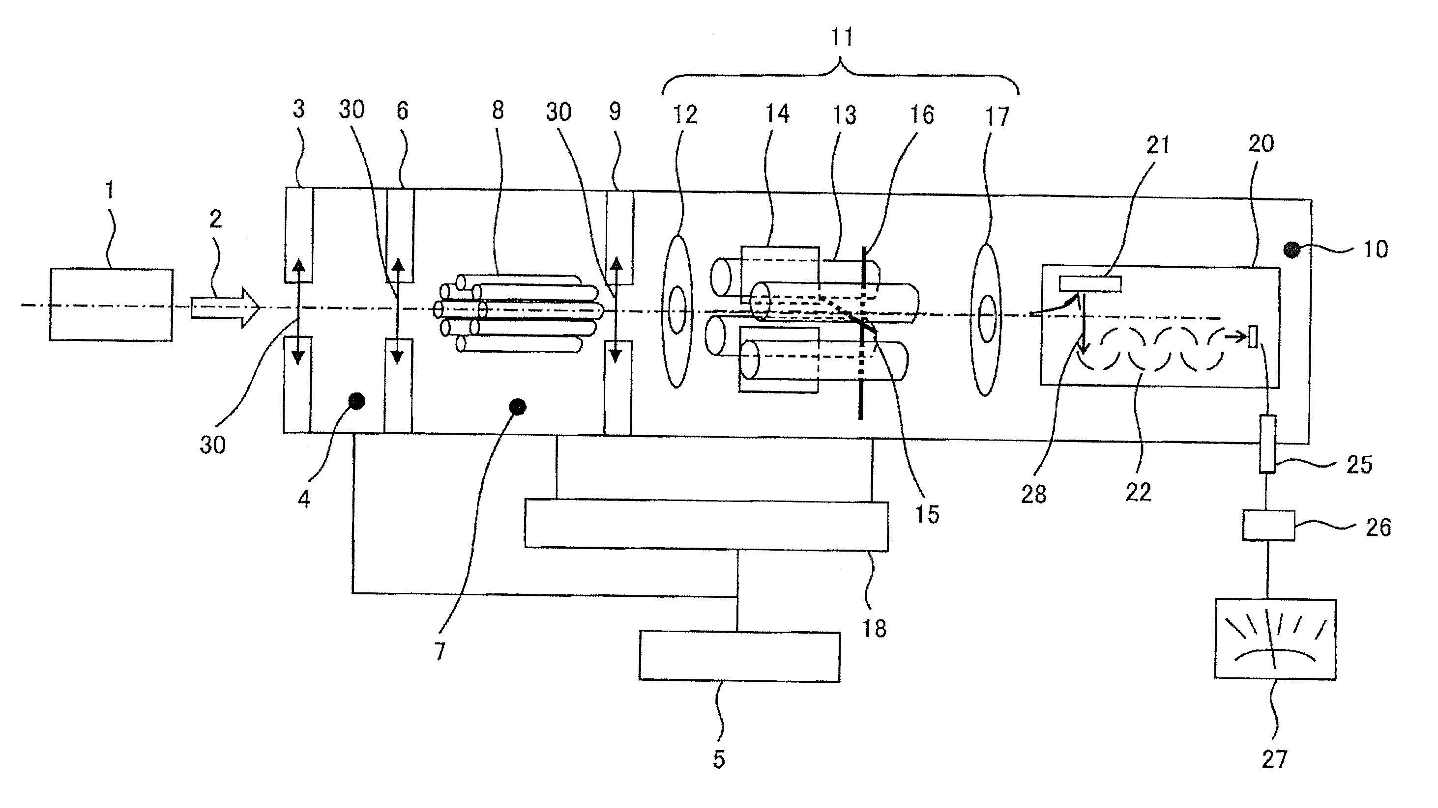
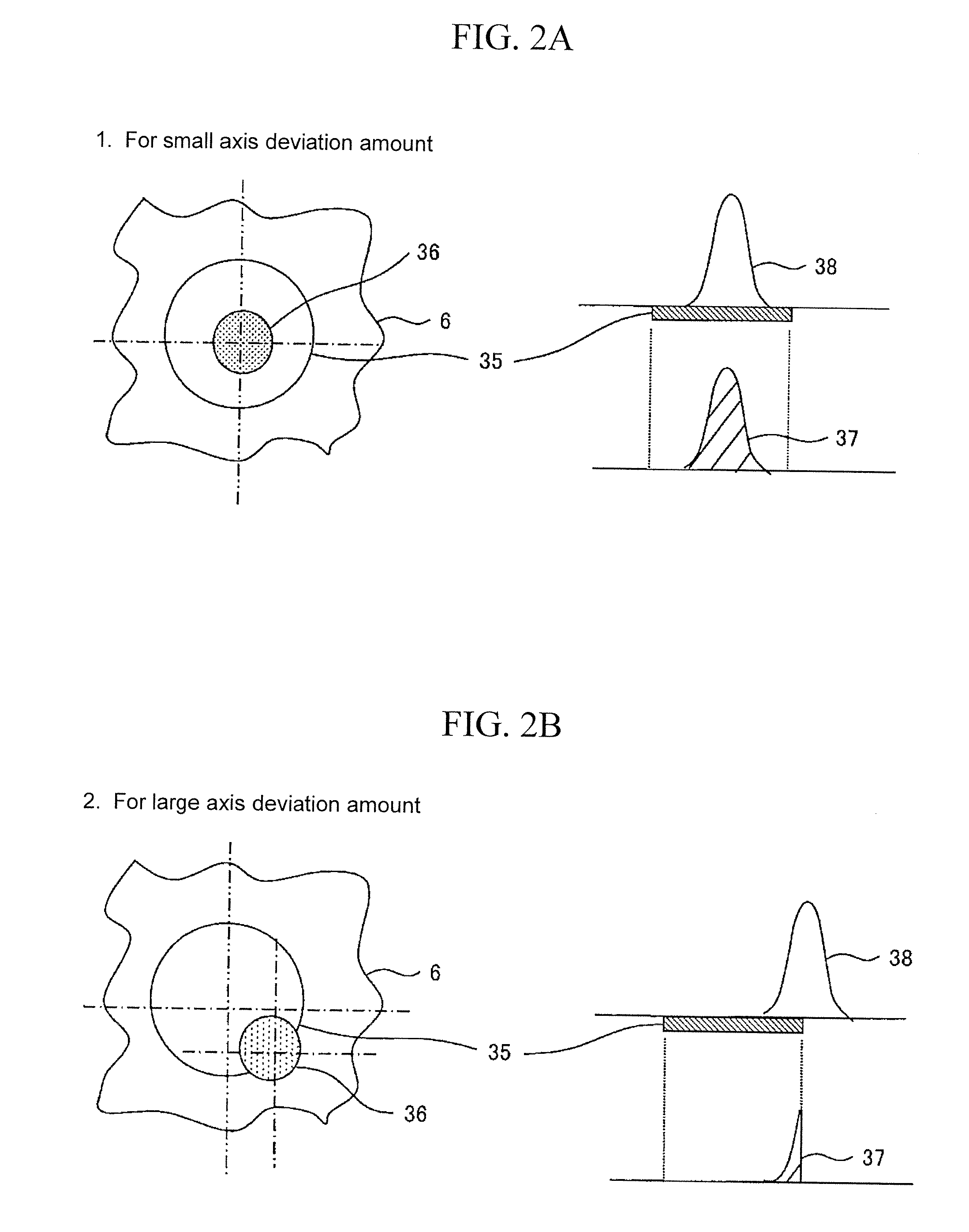
[0013]According to the invention, the center axis of the component located between the ion source and the detector, particularly the center axis of the orifice and an ion beam traveling axis connecting a beam outgoing axis of the ion source and an incident port axis of the detector can substantially be aligned with each other to minimize the axis deviation amount, so that the number of ions reaching the detector can be maximized. Therefore, the vacuum pump can be miniaturized, and the compact, light-weight, high-sensitivity, high-resolution mass spectrometer can be implemented.

Problems solved by technology

When a degree of vacuum in a vacuum vessel of a mass spectrometer is low, the ion collides with a residual gas molecule in the vacuum vessel at a number of times, and loses its charge due to exchange of charges or changes its traveling direction due to collision, whereby the number of ions reaching the detector is decreased to hardly perform correct mass spectrometry.
By decreasing the mechanical tolerance of each component, the axis deviation amount can be decreased but the apparatus becomes expensive.
A sample gas adheres to a surface of the orifice to form an insulating film on the surface of the orifice, which results in a problem such that a drift of the ion beam is generated due to accumulation of charge.
The temperature of the orifice changes depending on the time elapsed after the start-up of the apparatus, and a thermal expansion amount also changes, which results in a problem such that the axis deviation amount changes transiently.
Examples of the problems include sensitivity degradation and resolution degradation of a mass spectrometer, which are caused by an axis deviation of a component, particularly at least one orifice, located between an ion source and a detector, to decrease the number of ions reaching the detector, and a variation in performances caused by exchange of components such as the orifice.

Method used


Image

  • Mass spectrometer
  • Mass spectrometer
  • Mass spectrometer

Examples


first embodiment

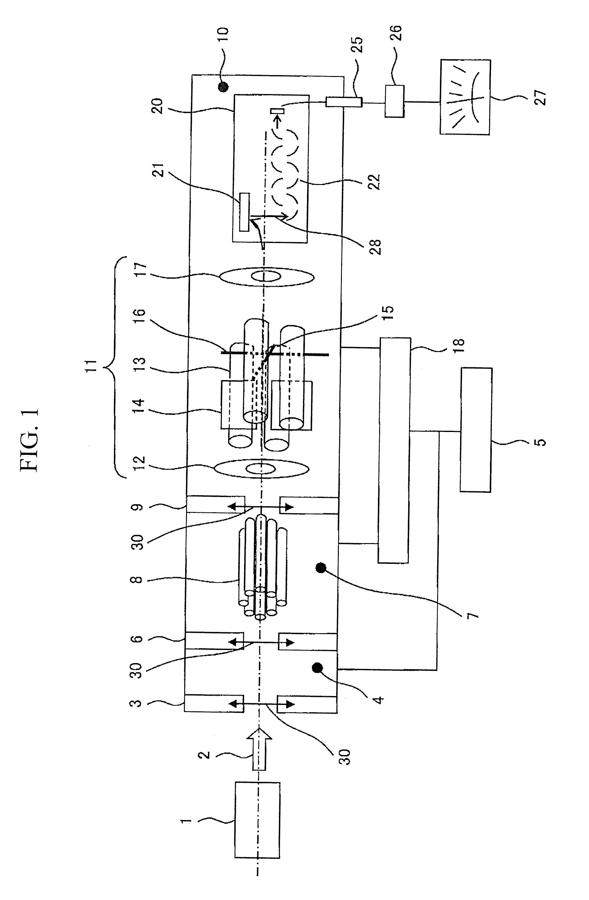
[0043]FIG. 3 illustrates an entire configuration of an apparatus in which APCI (Atmospheric Pressure Chemical Ionization) is used as the ion source in the apparatus of FIG. 1. In FIG. 1, the octopole 8 and the quadrupole mass separator 11 are illustrated in the perspective views. On the other hand, in FIG. 3, the octopole 8 and the quadrupole mass separator 11 are illustrated in a plan view. Hereinafter, the overlapping description is omitted.

[0044]Air 45 is taken in the ion source 1 by a suction pump 40. At this point, TCP (trichlorophenol) that is of a standard sample 41 is heated and vaporized by a heater 42. After a vaporized gas amount becomes constant while the standard sample 41 is maintained at a constant temperature, a flow rate of the air 45 is set through a filter 44 by a mass flow controller 43. The heater 42 is wound around pipe 46 located on a downstream side such that adhesion of a vaporized component of TCP to the pipe 46 is suppressed as much as possible. A voltage ...

second embodiment

[0061]FIG. 8 illustrates a TOF (Time Of Flight) mass spectrometer provided with the axis adjusting mechanism. The ion is accelerated in the orthogonal direction by an acceleration electric field of several hundreds of volts to several kilovolts applied to a push-out electrode 71 and an acceleration pull-out electrode 72, the ion deflects through the ion reflector 73 which is called a reflector reaches the detector, and the ion reaches the detector such as a multi channel plate 74. The variation in initial energy of the ion is corrected to equalize a total flight time of the ions having the identical mass-to-charge ratio m / z using the reflector, so that mass resolution can be enhanced.

[0062]The miniaturization of the mass spectrometer can also be implemented by utilizing the axis adjusting mechanism 30 in each orifice.


PUM


Abstract

An object of the present invention is to provide means for solving troubles. Examples of the troubles include sensitivity degradation and resolution degradation of a mass spectrometer, which are caused by an axis deviation of a component, particularly at least one orifice located between an ion source and a detector, to decrease the number of ions reaching the detector, and a variation in performance caused by exchange of components such as the orifice.For example, the invention has the following configuration in order to solve the troubles. A mass spectrometer includes: an ion source; a detector that detects an ion; an orifice and a mass separator that are disposed between the ion source and the detector; and an axis adjusting mechanism that adjusts axis positions of the orifice and / or the mass separator such that an opening of the orifice and / or an incident port of the mass separator is disposed on a line connecting the ion source and an incident port of the detector.

Description

BACKGROUND OF THE INVENTION[0001]1. Field of the Invention[0002]The present invention relates to a mass spectrometer, particularly to miniaturization and weight reduction of the mass spectrometer.[0003]2. Description of the Related Art[0004]In a mass spectrometer, a molecule or an atom as an analytical target is ionized, and the ions are transported in vacuum to be subjected to mass separation by utilizing an electric field and a magnetic field. The separated ions are detected by a detector. When a degree of vacuum in a vacuum vessel of a mass spectrometer is low, the ion collides with a residual gas molecule in the vacuum vessel at a number of times, and loses its charge due to exchange of charges or changes its traveling direction due to collision, whereby the number of ions reaching the detector is decreased to hardly perform correct mass spectrometry. Therefore, the degree of vacuum is set to be about 10−3 Pa or less in a spatial area of a vacuum chamber in which a mass separato...

Claims


Application Information

Patent Timeline
Patent Type & Authority Patents(United States)
IPC IPC(8): B01D59/44H01J49/00
CPCH01J49/067H01J49/04H01J49/0013
Inventor ISHIGURO, KOUJIMOROKUMA, HIDETOSHI
Owner HITACHI HIGH-TECH CORP
Learn More