
Haymaking machine provided with a hitching device with an inclined pivoting axis

a technology of haymaking machine and pivoting axis, which is applied in the direction of haymakers, ploughs, spades, etc., can solve the problems of lateral tilting of the machine, major defect of the machine, and risk of the stability of the machine, so as to reduce the torsional stress, improve the overall efficiency of the invention, and prolong the life of the machine

Inactive Publication Date: 2013-11-12
KUHN SA
View PDF20 Cites 4 Cited by
  • Summary
  • Abstract
  • Description
  • Claims
  • Application Information

AI Technical Summary

Benefits of technology

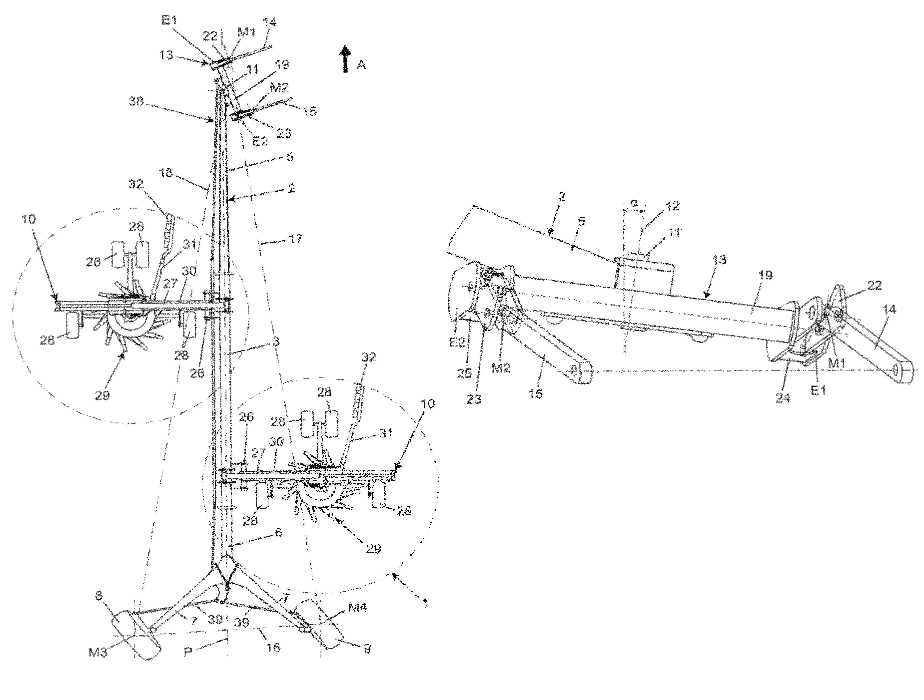
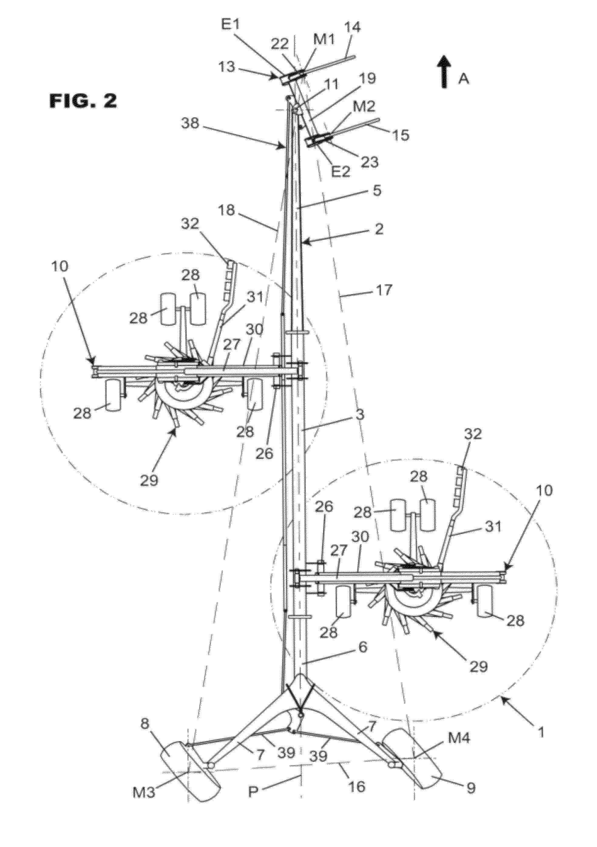
[0012]The result of this is that when the frame pivots with respect to the hitching device about this axis so as to follow a curved course, the end of the hitching device situated on the interior side of the course is at a greater height than the opposite end, which generates a greater support on the lower arm situated on the exterior side of the course, whereas the lower arm situated on the interior side of the course is relieved. The sustentation triangle is then forced to pass through the articulation between the hitching device and the lower arm situated on the exterior side of the course. This reduces the risk that, under the effect of a lateral acceleration such as centrifugal acceleration, the center of gravity leaves the sustentation triangle and that the machine tilts towards the exterior of the course.
[0014]The machine can then advantageously be hitched to a tractor, the lower arms of which are held parallel to each other. In addition, the yokes allow the axis of the pivoting connection to be greatly inclined towards the front, which contributes to an improvement of the overall efficiency of the invention. Furthermore, through the additional degree of freedom which they give to the hitching device in its movements with respect to the lower arms, the yokes reduce the torsional stresses which exert on the frame, and extend the lifespan of the machine.

Problems solved by technology

However, when the machine undergoes a lateral acceleration, it can occur that the machine rests on only one of the lower arms, in which case the previously described machine has a major defect.
This uncertainty represents a risk for the stability of the machine, which is aggravated by the fact that, when the machine is in the transport position, its center of gravity is situated at a great distance from the ground owing to the vertical extension of the work devices.
In this situation, the centrifugal force can cause the center of gravity to leave the sustentation triangle, which causes the lateral tilting of the machine.
The result of this is that the farmer must slow the tractor down greatly on turns.
Thus, when the machine follows a curved course, it is even more easily destabilized than in the transport position.
To reduce this risk, the farmer must travel at a reduced speed over his plot of land, which slows him down in his work.

Method used


Image

  • Haymaking machine provided with a hitching device with an inclined pivoting axis
  • Haymaking machine provided with a hitching device with an inclined pivoting axis
  • Haymaking machine provided with a hitching device with an inclined pivoting axis

Examples


Embodiment Construction

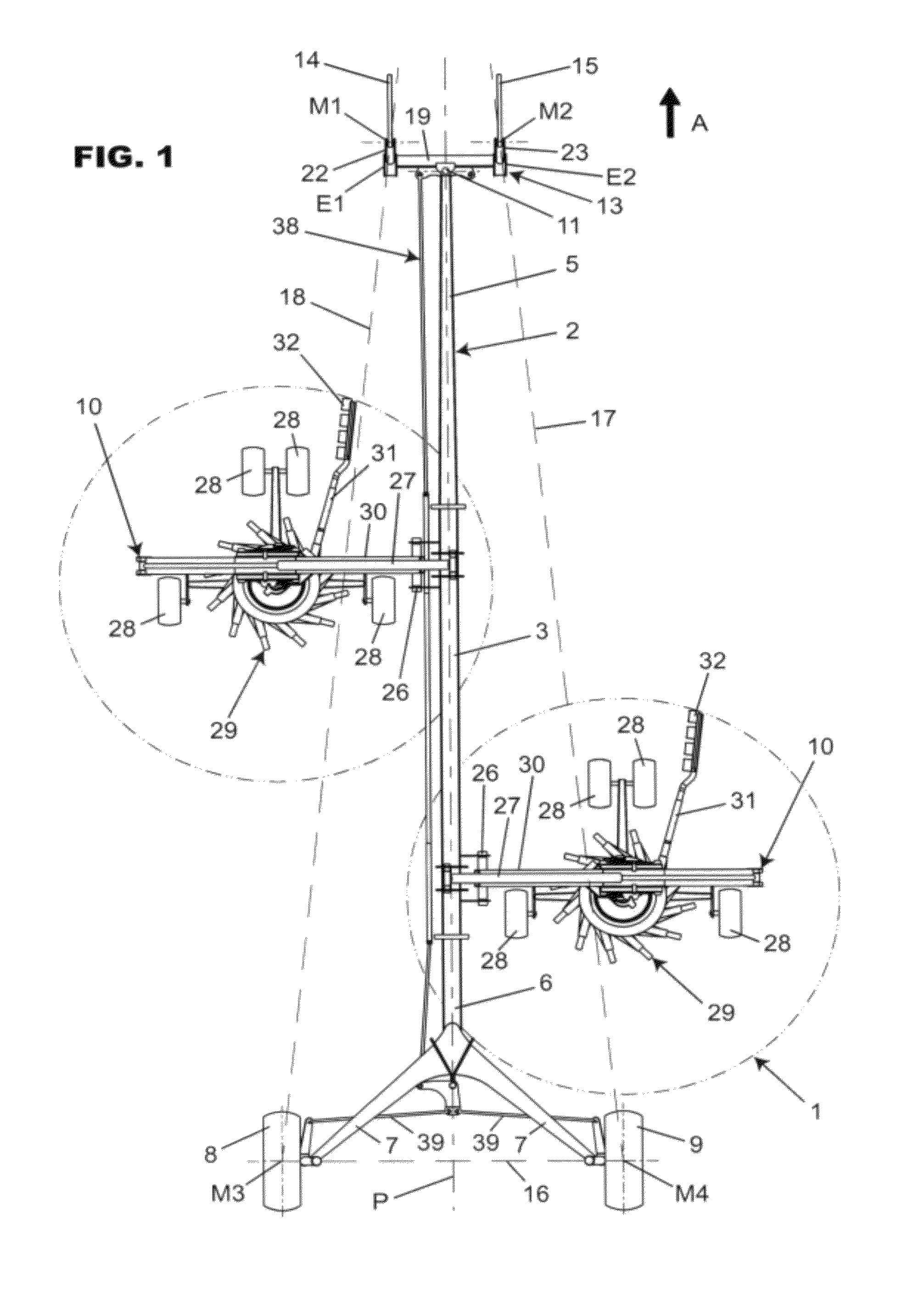
[0027]As can be seen from FIG. 1, the machine 1 according to the invention comprises a frame 2. The latter comprises a central beam 3 which is substantially horizontal. In the variant embodiment presented in FIGS. 1 to 3, the central beam 3 is extended in its part situated towards the tractor 4—represented partially in FIG. 3—by a front beam 5 rigidly linked to the central beam 3 and which is inclined towards the ground. At its rear end, the central beam 3 is extended by a rear beam 6 rigidly linked to the central beam 3 and which is inclined towards the ground. The rear beam 6 is rigidly fastened to two divergent supports 7 each having a wheel 8, 9 which rests on the ground. The machine 1 according to the invention could comprise more than two wheels. At least one work device 10 is connected to the central beam 3. The tractor 4 serves to move the machine in a direction of advance A and to drive the work devices 10. The front beam 5 has a pivoting connection 11 having an axis 12 wit...


PUM


Abstract

An agricultural haymaking machine intended to be hitched to the lower arms of a tractor comprises a frame supported on the ground by wheels and at least one work device connected to the frame, the frame being in its front part in pivoting connection with a hitching device configured to be connected to the two lower arms, the center of gravity of the machine being situated between the wheels and the hitching device. According to the invention, the projection of the axis of the pivoting connection, on a plane which is substantially vertical and substantially parallel to the direction of advance, has an inclination towards the direction of advance following a direction of the ground upward.

Description

BACKGROUND OF THE INVENTION[0001]1. Field of the Invention[0002]The present invention relates to an agricultural haymaking machine intended to be hitched to the lower arms of a tractor and comprising:[0003]a frame supported on the ground by wheels,[0004]at least one work device connected to the frame, the frame being in pivoting connection in its front part with a hitching device configured to be connected to the two lower arms, the center of gravity of the machine being situated between the wheels and the hitching device.[0005]2. Discussion of the Background[0006]Such a machine is known from the document FR 2 778 311. This document describes a windrowing machine of the semi-mounted type which comprises a frame, the front part of which is in pivoting connection with a hitching device configured to be hitched to the two lower arms situated at the rear of a tractor. The pivoting connection has a substantially vertical axis. The frame is supported in its rear part by two wheels. Two wo...

Claims


Application Information

Patent Timeline
Patent Type & Authority Patents(United States)
IPC IPC(8): A01D43/00A01D57/00
CPCA01D78/1042
Inventor HOERNER, YANNICK
Owner KUHN SA
Learn More