Modular lighting system

a module and lighting technology, applied in the field of module lighting systems, can solve the problems of long life of leds, disadvantages of using leds, and difficulty in connecting leds, and achieve the effect of quick and easy coupling

Active Publication Date: 2013-11-12
ECOTECH LLC
View PDF9 Cites 61 Cited by
  • Summary
  • Abstract
  • Description
  • Claims
  • Application Information

AI Technical Summary

Benefits of technology

[0006]It is therefore a primary object, feature, and / or advantage of the present invention to overcome deficiencies in the art.
[0007]It is another object, feature, and / or advantage of the present invention to provide a general purpose LED tube containing a pre-wired strip of LEDs.
[0008]It is yet another object, feature, and / or advantage of the present invention to provide an LED tube that can be used in any combination of light and spectral distribution.
[0009]It is still another object, feature, and / or advantage of the present invention to provide an LED tube that can be connected to multiple power supplies.
[0010]It is another object, feature, and / or advantage of the present invention to provide an LED tube that can be quickly and easily coupled to additional LED tubes.
[0011]It is another object, feature, and / or advantage of the present invention to provide an LED tube that includes an end that can snap into power supplies.

Problems solved by technology

In addition, LEDs have a much longer lifetime than either fluorescent or incandescent bulbs.
However, there are some disadvantages to using LEDs.
It may be difficult to wire the LEDs together.
It is also difficult to find the correct power source that correctly powers the LEDs, but that is also practical to use with the application of the light source.
Therefore, it is not practical to buy LEDs to put together for use in everyday applications.
In addition, it may be difficult to determine the correct amount of LEDs to use for a particular application.

Method used


Image

  • Modular lighting system
  • Modular lighting system
  • Modular lighting system

Examples


Embodiment Construction

[0030]The present invention will be described as it applies to its preferred embodiment. It is not intended that the present invention be limited to the described embodiment. It is intended that the invention cover all modifications and alternatives that may be included within the spirit and scope of the invention.

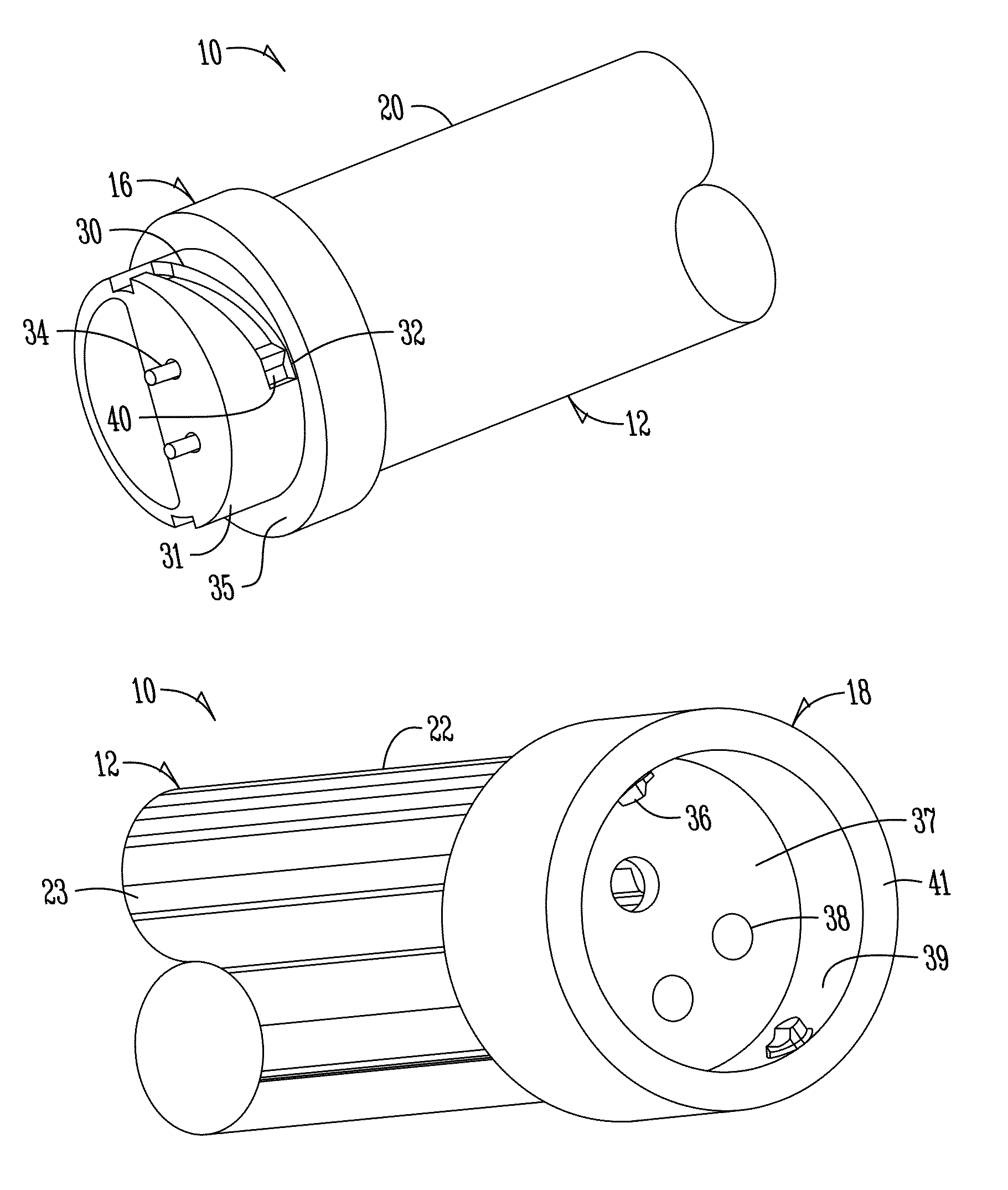
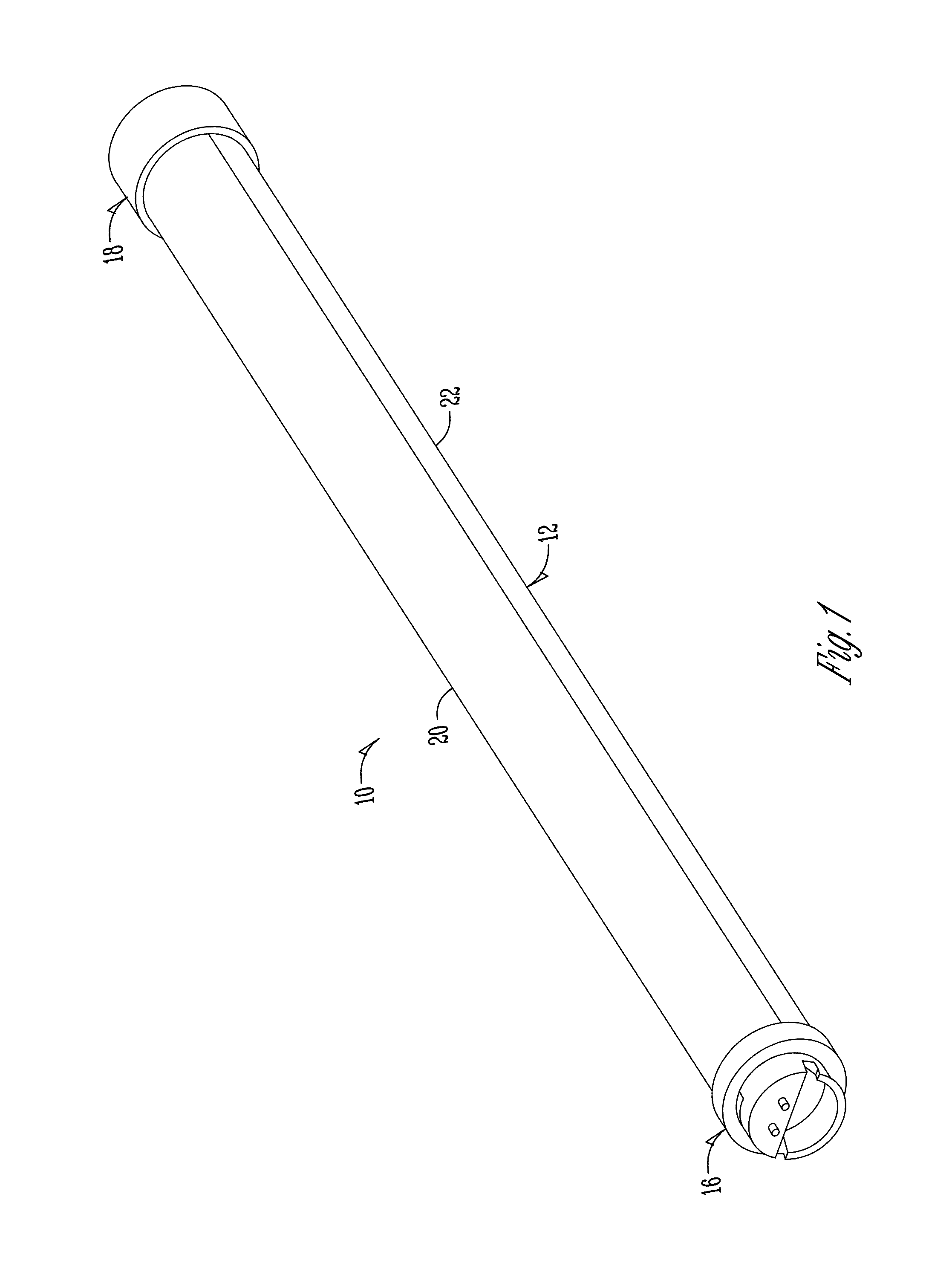
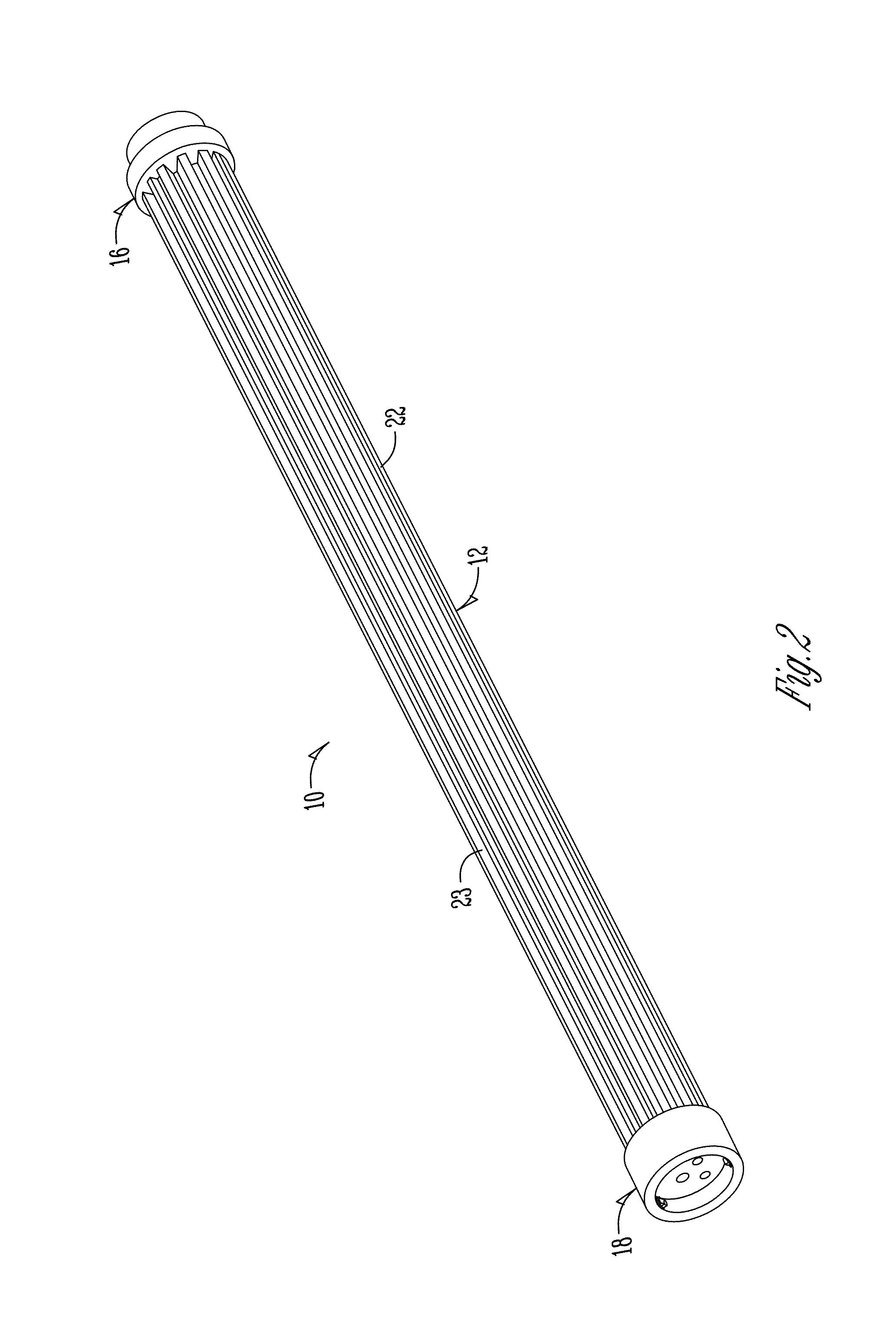
[0031]FIG. 1 shows a general purpose light-emitting diode (LED) tube 10 designed for general illumination. The LED tube can be used with any combination of light and spectral distribution. The tube is designed for low power consumption and can be powered by any power source. Examples of power sources for use with the LED tube are switching power supplies, offline supplies, battery packs, and solar power. However, it should be appreciated that these are just examples of power sources, and any power source may be used with the LED tube.

[0032]The LED tube comprises a tubular housing 12, an LED strip 14, a first end or plug connector 16, and a second end or jack close 18. The ...


PUM


Abstract

An LED tube is provided for providing general illumination. The LED tube includes a tubular housing having a clear shield and a heat sink opposite the clear shield. A strip including LED lights, circuitry, and electrical hubs are positioned on the backside of the heat sink under the shield. The housing also includes first and second ends that include portions of a quarter turn locking system to allow multiple housings to be attached to one another for a longer string of lighting. A power source for powering the LED lights, and an end cap may also be attached to the first and second ends of the housing by the quarter turn locking system. The housing or housings may be connected to a wall or the like by the use of one or more clip mounts.

Description

CROSS-REFERENCE TO RELATED APPLICATIONS[0001]This application claims priority under 35 U.S.C. §119 to provisional application Ser. No. 61 / 378,608 filed Aug. 31, 2010, herein incorporated by reference in its entirety.FIELD OF THE INVENTION[0002]The present invention generally relates to a lighting strip for providing general illumination. More particularly, but not exclusively, the invention relates to a lighting tube containing a strip of LED lights that can be easily attached to like tubes to provide for varying amounts and lengths of light.BACKGROUND OF THE INVENTION[0003]Light emitting diode (LED) lights, and more particularly, groups of LED lights, are currently used to illuminate a variety of areas. The lights are placed in clusters to provide a specifically oriented ray of light, as with a flashlight, or they are added to strips for illuminating a larger, more generalized area. Although a number of LEDs are needed to produce enough light to illuminate a desired area, LEDs do n...

Claims


Application Information

Patent Timeline
Patent Type & Authority Patents(United States)
IPC IPC(8): F21V21/00
CPCF21K9/30F21L4/00F21V29/89F21V19/008F21V29/74F21V17/14F21S2/005F21S9/03F21Y2101/02F21Y2103/003F21K9/20F21Y2103/10F21Y2115/10
Inventor CLOUGH, CHRISTIAN JAMES
Owner ECOTECH LLC
Why Eureka
Try Eureka