Independently controllable transmission mechanism

a transmission mechanism and independent control technology, applied in mechanical equipment, transportation and packaging, gearbox systems, etc., can solve the problems of transmission system, inability to variably control the power output, and inefficiency of transmission system,

Active Publication Date: 2013-11-19
NAT SUN YAT SEN UNIV
View PDF10 Cites 7 Cited by
  • Summary
  • Abstract
  • Description
  • Claims
  • Application Information

AI Technical Summary

Benefits of technology

[0007]The primary objective of this invention is to provide an independently controllable transmission mechanism, with two planetary gear sets and two transmission-connecting sets utilized to variably control power input and to variably control power output. The transmission mechanism includes a transmission control end and a free transmission end functioning as a power input end or a power output end by the transmission control end. The transmission mechanism shifts the free transmission end between the power input end and the power output end for independently controlling the power transmission. Accordingly, independently controlling the power transmission of the transmission mechanism can be successfully achieved.
[0008]Another objective of this invention is to provide an independently controllable transmission mechanism, with two planetary gear sets and two transmission-connecting sets utilized to variably control power input and to variably control power output. No frictionally sliding member is utilized in the transmission mechanism. Accordingly, the efficiency of the power transmission of the present invention can be successfully increased.

Problems solved by technology

With regard to the problematic aspects naturally occurring during use of the gearbox system, the transmission in the gearbox system is susceptible to inefficiency due to frictional slide movements of the slide in the gearbox.
However, the primary problem with such a transmission system is the powers generated from the first motor and the second motor must be constantly transmitted to the single transmission shaft via the first planetary gear set and the second planetary gear set.
The transmission system, however, cannot function to variably control the power output.

Method used


Image

  • Independently controllable transmission mechanism
  • Independently controllable transmission mechanism
  • Independently controllable transmission mechanism

Examples


first embodiment

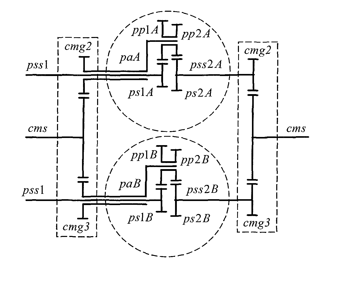
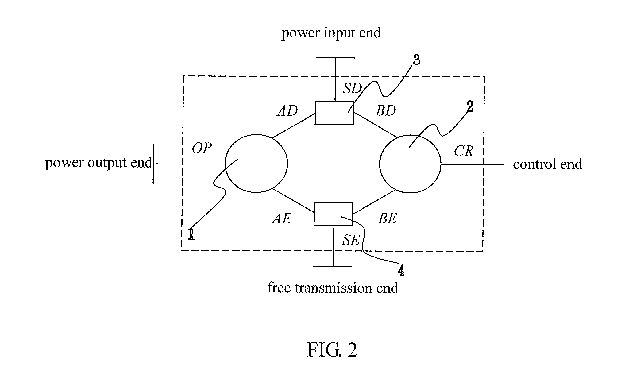
[0051]Referring again to FIGS. 2 and 5, in the first embodiment, the two planetary gear sets correspond to the first planetary gear set 1 and the second planetary gear set 2 and are comprised of two planetary gear sets each of which has a positive speed ratio. The two transmission-connecting sets correspond to the first transmission-connecting set 3 and the second transmission-connecting set 4. Two planetary-gear-arm rotational axles paA, paB and two central-gear rotational axles pss2A, pss2B of the two planetary gear sets mechanically connect with the two transmission-connecting sets. Two sun-gear rotational axles pss1 of the two planetary gear sets perform as the first power output end of the first planetary gear set 1 (i.e. first rotational axle OP) and the transmission control end of the second planetary gear set 2 (i.e. first rotational axle CR). Two rotational axles cms of the two transmission-connecting sets perform as the first power input end SD of the first transmission-co...

second embodiment

[0052]Referring again to FIGS. 2 and 6, in the second embodiment, the two planetary gear sets correspond to the first planetary gear set 1 and the second planetary gear set and are comprised of a planetary gear set having a positive speed ratio and a planetary gear set having a negative speed ratio. The two transmission-connecting sets correspond to the first transmission-connecting set 3 and the second transmission-connecting set 4. Two planetary-gear-arm rotational axles pa, na, a central-gear rotational axle pss2 and a ring-gear rotational axle nrs of the two planetary gear sets mechanically connect with the two transmission-connecting sets. Two sun-gear rotational axles pss1, nss of the two planetary gear sets perform as the first power output end of the first planetary gear set 1 (i.e. first rotational axle OP) and the transmission control end of the second planetary gear set 2 (i.e. first rotational axle CR). Two rotational axles cms of the two transmission-connecting sets per...

third embodiment

[0053]Referring again to FIGS. 2 and 7, in the third embodiment, the two planetary gear sets correspond to the first planetary gear set 1 and the second planetary gear set and are comprised of a planetary gear set having a positive speed ratio and a planetary gear set having a negative speed ratio. The two transmission-connecting sets correspond to the first transmission-connecting set 3 and the second transmission-connecting set 4. Two planetary-gear-arm rotational axles pa, na and two sun-gear rotational axles pss1, nss of the two planetary gear sets mechanically connect with the two transmission-connecting sets. A central-gear rotational axle pss2 and a ring-gear rotational axle nrs of the two planetary gear sets perform as the first power output end of the first planetary gear set 1 (i.e. first rotational axle OP) and the transmission control end of the second planetary gear set 2 (i.e. first rotational axle CR). Two rotational axles cms of the two transmission-connecting sets p...


PUM


Abstract

An independently controllable transmission mechanism includes a first planetary gear set, a second planetary gear set, a first transmission-connecting set and a second transmission-connecting set. The first planetary gear set includes a first power output end, the second planetary gear set includes a transmission control end, the first transmission-connecting set includes a first power input end and the second transmission-connecting set includes a free transmission end. The transmission control end controls the free transmission end to function as a second power input end or a second power output end.

Description

BACKGROUND OF THE INVENTION[0001]1. Field of the Invention[0002]The present invention relates to an independently controllable transmission mechanism. More particularly, the present invention relates to the independently controllable transmission mechanism utilizing two planetary gear sets and two transmission-connecting sets for variably controlling the power input and for variably controlling the power output.[0003]2. Description of the Related Art[0004]Taiwanese Patent Pub. No. I242521 discloses a conventional gearbox structure for vehicles, including a main shaft on which to provide a slide. A forward gear and a drive gear are arranged at each side of the slide. A transmission shaft is provided with a reverse slide and a combination of a backward bevel gear and a forward bevel gear adjacent to the reverse slide. A final gear shaft is arranged between the backward bevel gear and the forward bevel gear. The forward gear and the drive gear are also arranged between the backward bev...

Claims


Application Information

Patent Timeline
Patent Type & Authority Patents(United States)
IPC IPC(8): F16H37/02
CPCF16H3/72F16H2200/2007
Inventor HWANG, GUAN-SHYONGTSAY, DER-MIN
Owner NAT SUN YAT SEN UNIV
Why Eureka
Try Eureka