Converter circuit arrangement, as well as a method for matching a variable DC voltage

a converter circuit and voltage matching technology, applied in the field of power electronics, can solve the problems of only a major level of circuit complexity, and considerable costs

Inactive Publication Date: 2003-05-08
ABB (SCHWEIZ) AG
View PDF8 Cites 2 Cited by
  • Summary
  • Abstract
  • Description
  • Claims
  • Application Information

AI Technical Summary

Benefits of technology

[0007] The converter circuit arrangement according to the invention for matching a variable DC voltage has a drive circuit for producing drive signals, and a three-point DC voltage intermediate circuit. The three-point DC voltage intermediate circuit is formed by a first capacitor and a second capacitor connected in series with it, with one connection of the first capacitor forming an upper connection of the three-point DC voltage intermediate circuit, and the first capacitor forming a center point connection at the junction point with the second capacitor. Furthermore, one connection of the second capacitor forms a lower connection of the three-point DC voltage intermediate circuit. According to the invention, a first partial converter system and a second partial converter system are provided, with the input side of the first partial converter system being connected to a first pole of a DC voltage source which produces the DC voltage, and the input side of the second partial converter system being connected to a second pole of the DC voltage source. Furthermore, a first output of the first partial converter system is connected to the upper connection, and a first output of the second partial converter system is connected to the lower connection. In addition, a second output of the first partial converter system is connected in series with a second output of the second partial converter system via the center point connection. The converter circuit arrangement according to the invention advantageously makes it possible to generate an essentially constant intermediate circuit voltage in the DC voltage intermediate circuit, with the first partial converter system essentially producing a constant first intermediate circuit voltage across the first capacitor, and the second partial converter system essentially producing a constant intermediate circuit voltage across the second capacitor. Power capacitors in a three-point converter circuit which is fed from the three-point DC voltage intermediate circuit may thus be designed for the essentially constant intermediate circuit voltage and need not be derated to provide a large voltage margin, thus making it possible to save considerable costs. Furthermore, there is no need for a costly and complicated drive circuit for driving the power switches in the three-point converter circuit, in order to allow controlled power transmission to an electrical AC voltage supply network. In addition, the converter circuit arrangement manages with a minimum number of components, and can be produced with a low level of circuit complexity. Furthermore, the converter circuit arrangement according to the invention is regarded as being convenient for maintenance and repair, owing to the simple construction and the small number of components.
[0008] In the method according to the invention for matching the variable DC voltage by means of the converter circuit arrangement according to the invention as described above, the first partial converter system is driven such that the first intermediate circuit voltage is set to an intermediate circuit voltage nominal value which can be predetermined. Furthermore, the second partial converter system is driven such that the second intermediate circuit voltage is set to the intermediate circuit voltage nominal value which can be predetermined. This way of driving the partial converter systems advantageously produces an essentially constant intermediate circuit voltage, in particular the first and second intermediate circuit voltages, in a very simple manner. The three-point converter circuit which is normally connected to the three-point DC voltage intermediate circuit accordingly and advantageously does not require any complicated drive procedure, designed for a variable DC voltage, for the power switches in the three-point converter circuit. Furthermore, the three-point DC voltage intermediate circuit can be successfully stabilized using the method according to the invention.

Problems solved by technology

One problem with a three-point converter circuit such as this is that power switches in the three-point converter circuit must be designed to switch a wide range of DC voltage from the DC voltage source to this range, in particular in terms of power.
However, this result in considerable costs, in which case consideration must also be given to providing a sufficient voltage margin in the design.
However, such voltage margins are at the moment provided only by very expensive components, and / or this can be done only with a major level of circuit complexity.
Since the DC voltage source is connected directly to the three-point DC voltage intermediate circuit, the intermediate circuit voltage is correlated with the variable DC voltage, so that controlled power transmission into an electrical AC voltage supply network is possible only via a costly and complicated drive circuit for driving the power switches in the three-point converter circuit.

Method used


Image

  • Converter circuit arrangement, as well as a method for matching a variable DC voltage
  • Converter circuit arrangement, as well as a method for matching a variable DC voltage
  • Converter circuit arrangement, as well as a method for matching a variable DC voltage

Examples


first embodiment

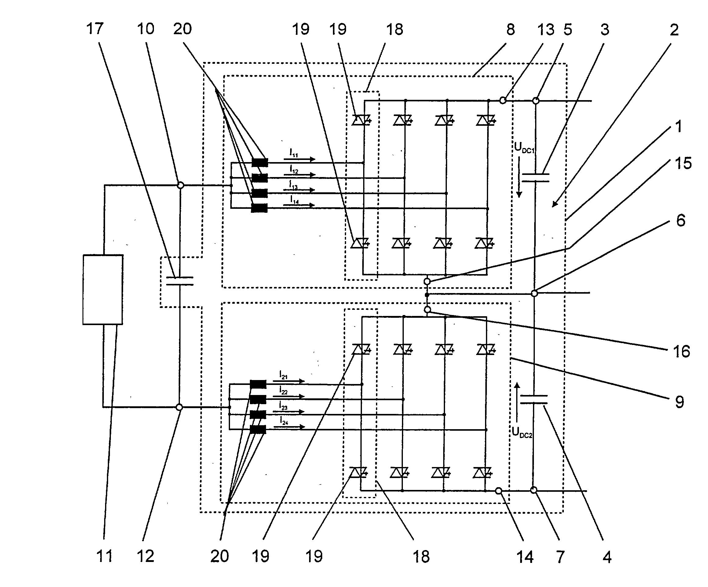
[0011] FIG. 1 shows a converter circuit arrangement according to the invention,

second embodiment

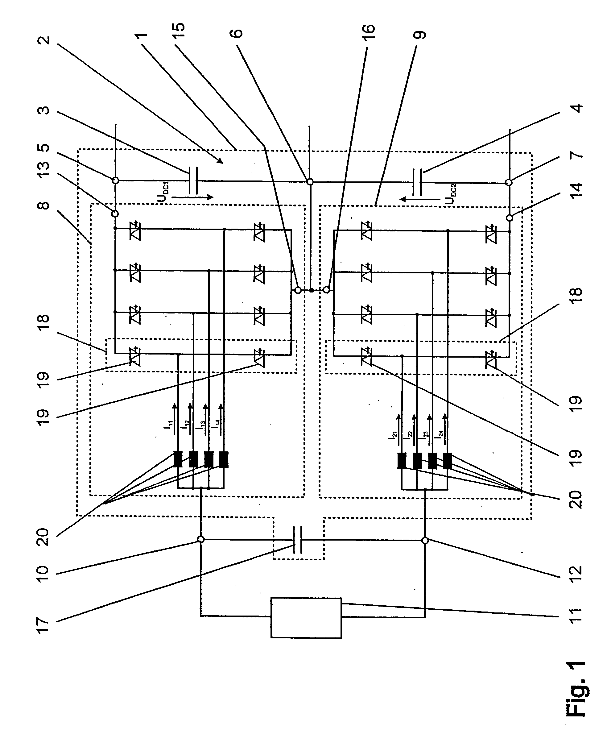
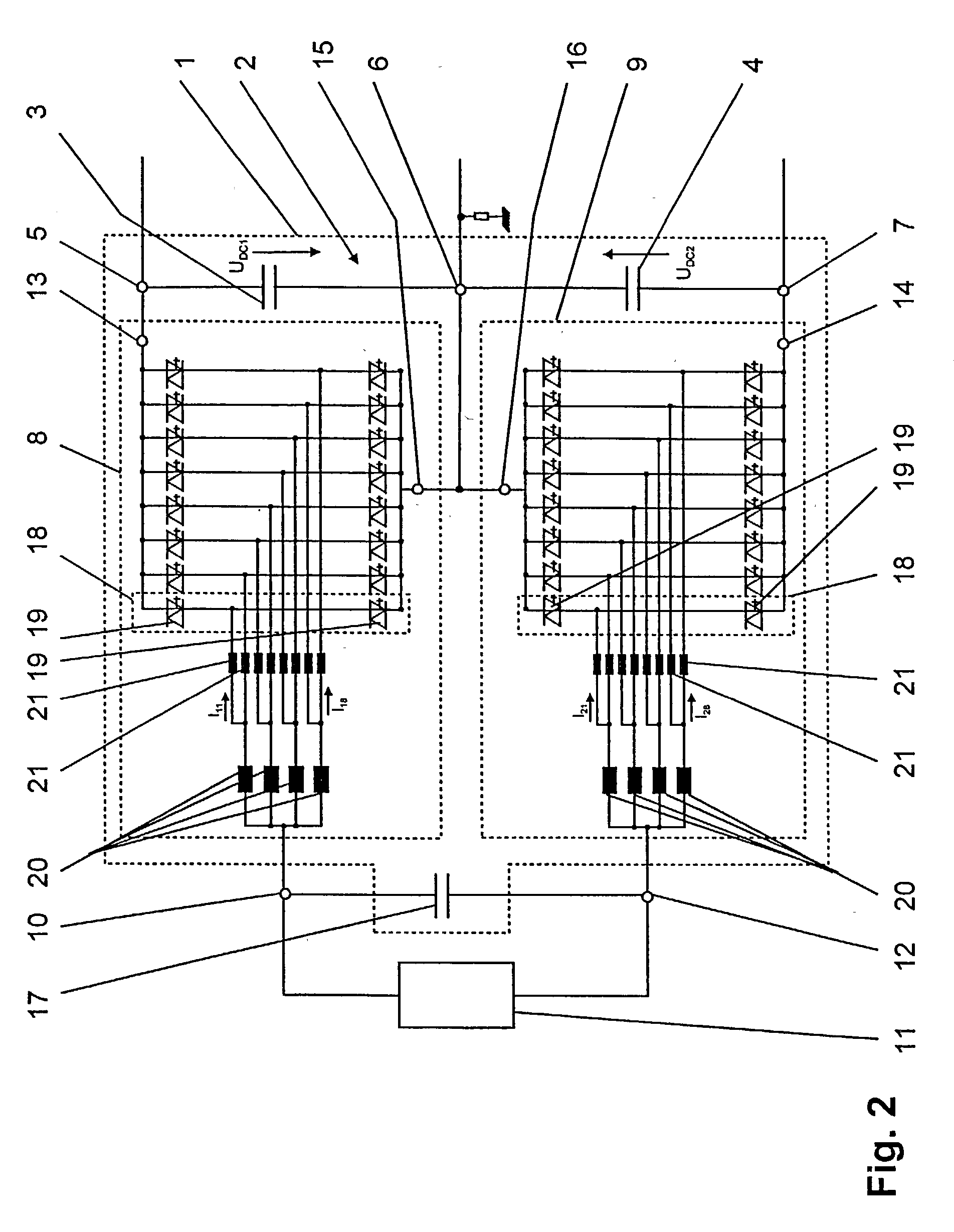
[0012] FIG. 2 shows a converter circuit arrangement according to the invention, and

[0013] FIG. 3 shows an embodiment of a drive circuit of a converter circuit arrangement according to the invention.

[0014] The reference symbols used in the drawing and their meanings are listed in summarized form in the list of reference symbols. In principle, identical parts are provided with the same reference symbols and figures. The described embodiments represent examples of the subject matter of the invention and have no restrictive effect.

[0015] Approaches to Implementation of the Invention

[0016] FIG. 1 shows a first embodiment of a converter circuit arrangement 1 according to the invention for matching a variable DC voltage. The converter circuit arrangement 1 comprises a drive circuit 28 for producing drive signals S.sub.11 . . . S.sub.1n; S.sub.21 . . . S.sub.2n, and one embodiment of such a drive circuit 28 is illustrated in FIG. 3 and will be described later. Furthermore, the converter cir...


PUM


Abstract

A converter circuit arrangement is disclosed for matching a variable DC voltage to a drive circuit for producing drive signals and having a three-point DC voltage intermediate circuit (2), which three-point DC voltage intermediate circuit (2) is formed by a first capacitor (3) and a second capacitor (4) connected in series with it, with one connection of the first capacitor (3) forming an upper connection (5) of the three-point DC voltage intermediate circuit (2), and the first capacitor (3) forming a center point connection (6) at the junction point with the second capacitor (4) and one connection of the second capacitor (4) forming a lower connection (7) of the three-point DC voltage intermediate circuit (2). A first partial converter system (8) and a second partial converter system (9) are provided, with the input side of the first partial converter system (8) being connected to a first pole (10) of a DC voltage source (11) which produces the DC voltage, and the input side of the second partial converter system (9) being connected to a second pole (12) of the DC voltage source (11), a first output (13) of the first partial converter system (8) being connected to the upper connection (5), and a first output (14) of the second partial converter system (9) being connected to the lower connection (7). Furthermore, a second output (15) of the first partial converter system (8) is connected in series with a second output (16) of the second partial converter system (9) via the center point connection (6). A method for matching a variable DC voltage is also specified.

Description

DESCRIPTION[0001] 1. Technical Field[0002] The invention relates to the field of power electronics and is based on a converter circuit arrangement and a method for matching a variable DC voltage as claimed in the precharacterizing clause of the independent claims.[0003] 2. Prior Art[0004] Two-pole DC voltages sources having a variable DC voltage on the output side are known, for example, from fuel cell applications, with the fuel cell representing such a DC voltage source with a variable DC voltage. Normally, owing to the different DC voltage level, such a DC voltage source feeds a three-point DC voltage intermediate circuit, which is formed by a first capacitor and a second capacitor connected in series with it. One connection of the first capacitor furthermore forms an upper connection of the three-point DC voltage intermediate circuit, and one connection of the second capacitor forms a lower connection of the three-point DC voltage intermediate circuit. Furthermore, a center poin...

Claims


Application Information

Patent Timeline
Patent Type & Authority Applications(United States)
IPC IPC(8): H02M3/158H02M3/135H02M7/48H02M7/487
CPCH02M7/487H02M3/158
Inventor DAHLER, PETERGAUPP, OSVIN
Owner ABB (SCHWEIZ) AG
Why Eureka
Try Eureka