Connector assembly suited for wet locations

a technology of connector assemblies and connector assemblies, applied in the direction of non-disconnectible pipe joints, applications, machine supports, etc., can solve the problems of insufficient protection, electrical and mechanical components are susceptible to contamination, and components brought together by connector assemblies can be sensitive to contaminants

Active Publication Date: 2013-11-19
ATKORE STEEL COMPONENTS INC
View PDF23 Cites 33 Cited by
  • Summary
  • Abstract
  • Description
  • Claims
  • Application Information

AI Technical Summary

Benefits of technology

[0007]Referring initially to FIG. 1, an exemplary connector assembly 100 includes a connector body 150, a compression ring 130, a compression nut 120, and a sealing ring 140, each of which is preferably cylindrical. As shown in FIG. 2, the connector body 150 may be inserted in the compression nut 120, with the compression nut 120 pressing against the compression ring 130, the compression ring 130 pressing against the sealing ring 140, and the sealing ring 140 pressing against the connector body 150. An optional conduit 110 may be inserted through the compression nut 120. The compression ring 130 helps secure the conduit 110 to the connector assembly 100. The pressing of the sealing ring 140 against the connector body 150 helps form a superior seal between the connector body 150 and the conduit 110. This seal resists contaminants such as dust and moisture. The interaction of the various components is further discussed below.
[0023]Returning to FIG. 6, an internal sealing gasket 850 and an external sealing gasket 855 enhance the ability of the connector assembly 100 to seal from contaminants such as dust and moisture. With the coupling body connector 700 shown in FIGS. 7A and 7B, the internal sealing gasket 850 is positioned within the connector first axial end 705, and the external sealing gasket 855 is positioned about the connector second axial end 710 (not pictured).

Problems solved by technology

The components brought together by connector assemblies can be sensitive to contaminants such as dust and moisture.
If a proper seal is not formed between and among the elements of the connector assembly, the electrical and mechanical components are susceptible to contamination and thus not adequately protected.
Additionally, traditional connector assemblies are not able to accommodate both threaded and unthreaded conduits.

Method used


Image

  • Connector assembly suited for wet locations
  • Connector assembly suited for wet locations
  • Connector assembly suited for wet locations

Examples


Embodiment Construction

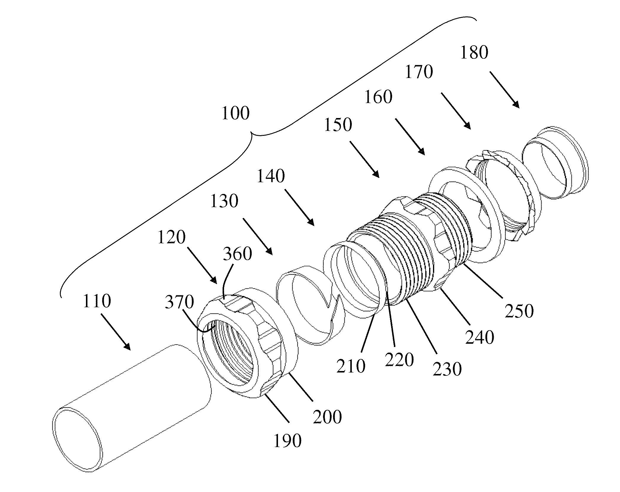
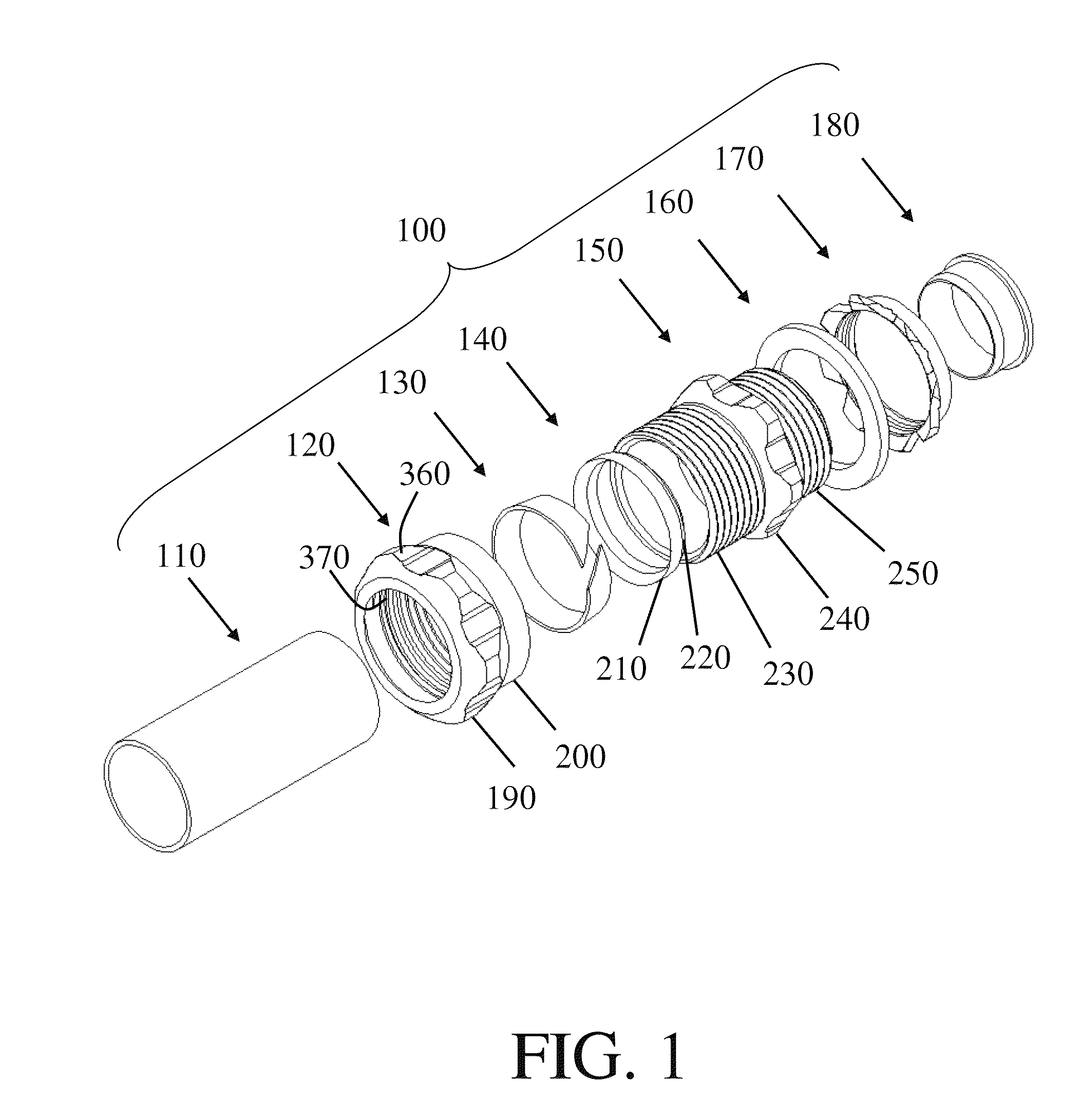
[0038]Continuing the discussion in the Summary section, the configuration of the connector assembly 100 shown in FIG. 1 is merely exemplary, and the numbers and types of components used in an assembly can be changed as desired. For example, connector bodies 150 and compression nuts 120 can be added or taken away, and the selected components can be interfaced together as needed, optionally using additional compression rings 130 and sealing rings 140 to secure conduits 110 and to enhance the seal formed between the selected components. Another compression nut 120, compression ring 130, and sealing ring 140 can be interfaced with the connector first axial end 250, for example, so that connector body 150 bridges two conduits 110.

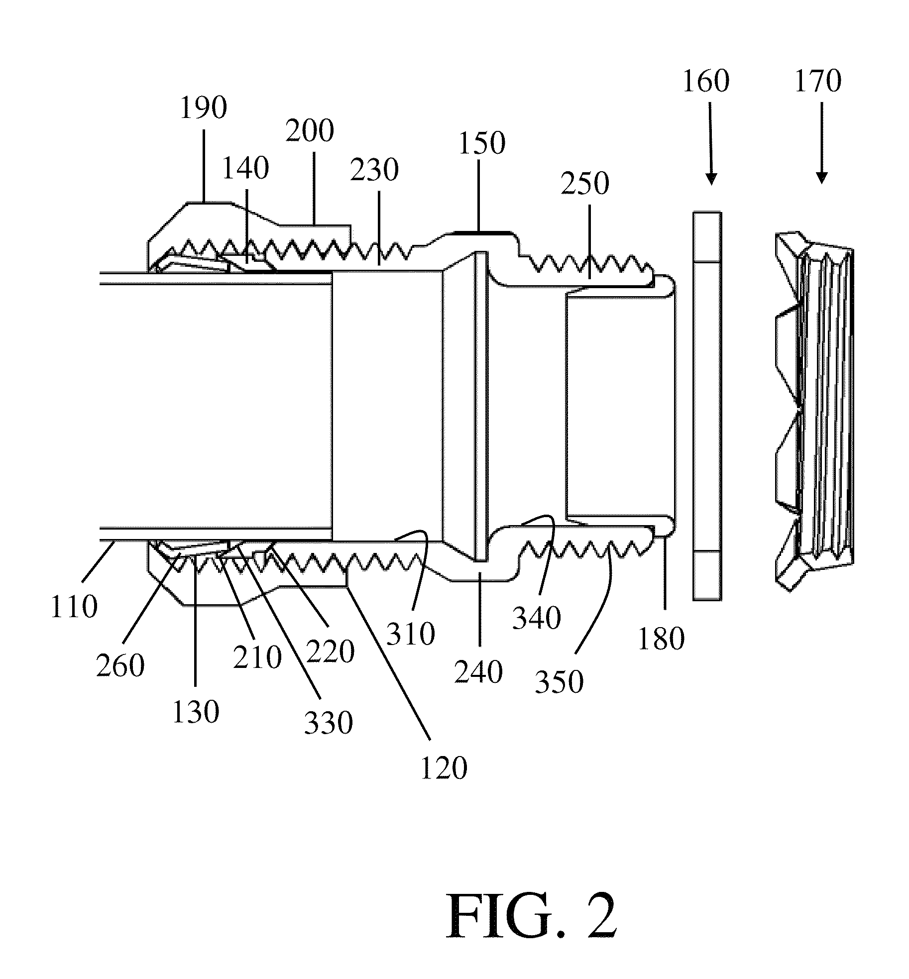
[0039]The inner and outer surfaces of the components can be substantially smooth, irregular, or threaded so that they can be slid past each other, gripped, or screwed together as needed. Additionally, the diameters of their various ends can be adjusted to permit...


PUM


Abstract

A compression ring includes an outer surface opposing an inner surface, with teeth extending radially inwardly from the inner surface. First and second circumferential ends are complementarily interfittable, and are separated by a circumferential gap, allowing the compression ring to be compressable when being installed in a connector assembly. First and second axial ends of the compression ring are chamfered to facilitate compression. The teeth extend circumferentially from the first and second circumferential ends and are complementary to conduit threading. Each tooth includes first and second sides, with the first side perpendicular to the inner surface to resist pullout of a conduit from the connector assembly. The teeth terminate in sharp points for better gripping of unthreaded conduits. A compressed compression ring accommodates threaded conduits by complementarily mating with threading, and unthreaded conduits by biting into their outer surfaces. Internal and external sealing gaskets provide seals from moisture.

Description

CROSS-REFERENCE TO RELATED APPLICATIONS[0001]This application is a continuation-in-part of U.S. patent application Ser. No. 12 / 725,502 filed Mar. 17, 2010 now U.S. Pat. No. 8,129,633, which is incorporated by reference herein.FIELD OF THE INVENTION[0002]This document concerns an invention relating generally to connector assemblies suited for wet locations.BACKGROUND OF THE INVENTION[0003]Electrical and mechanical components such as cables often need to be connected with each other through various angles and configurations. Conduits (such as pipes) and junction boxes may be used to house electrical cables, and connectors are used to join conduits with each other and / or with other components such as junction boxes in desired configurations. For example, U.S. Pat. No. 7,635,816 to Shemtov discloses a connector / bushing assembly for electrical junction boxes. Connector assemblies make use of such connector elements as connector bodies, nuts, gaskets, and bushings to provide the configura...

Claims


Application Information

Patent Timeline
Patent Type & Authority Patents(United States)
IPC IPC(8): H02G3/18
CPCF16L19/061H02G3/0675F16L19/065H01R13/52H01R9/0527
Inventor SHEMTOV, SAMI
Owner ATKORE STEEL COMPONENTS INC
Why Eureka
Try Eureka