Heat exchanger for outdoor enclosures

a technology of heat exchanger and outdoor enclosure, which is applied in the direction of indirect heat exchanger, light and heating apparatus, stationary plate conduit assembly, etc., can solve the problems of affecting the operation of electronic equipment, etc., and achieves the effect of improving the efficiency of the equipmen

Active Publication Date: 2013-11-26
ASYMBLIX
View PDF29 Cites 38 Cited by
  • Summary
  • Abstract
  • Description
  • Claims
  • Application Information

AI Technical Summary

Problems solved by technology

One problem with this approach is that the outside air may be contaminated with moisture and / or dust.
The moisture and / or dust in the outside air may adversely affect the operation of the electronic equipment.
This problem may be particularly troublesome in outdoor installations wherein the equipment cabinet is exposed to all elements of the weather.
This approach, however, also has problems.

Method used


Image

  • Heat exchanger for outdoor enclosures
  • Heat exchanger for outdoor enclosures
  • Heat exchanger for outdoor enclosures

Examples


Embodiment Construction

[0019]The making and using of the presently preferred embodiments are discussed in detail below. It should be appreciated, however, that the present invention provides many applicable inventive concepts that can be embodied in a wide variety of specific contexts. The specific embodiments discussed are merely illustrative of specific ways to make and use the invention, and do not limit the scope of the invention.

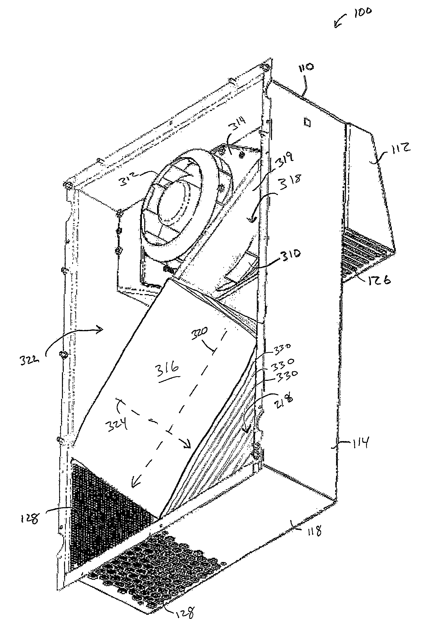
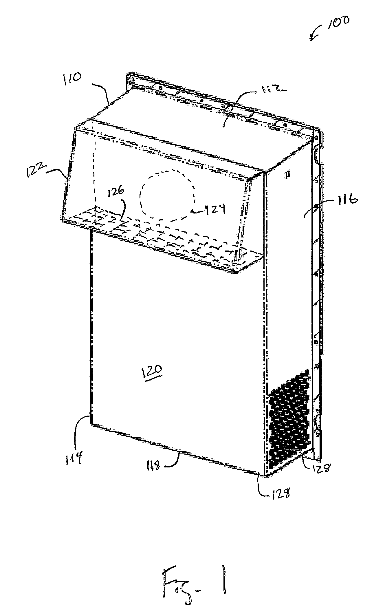
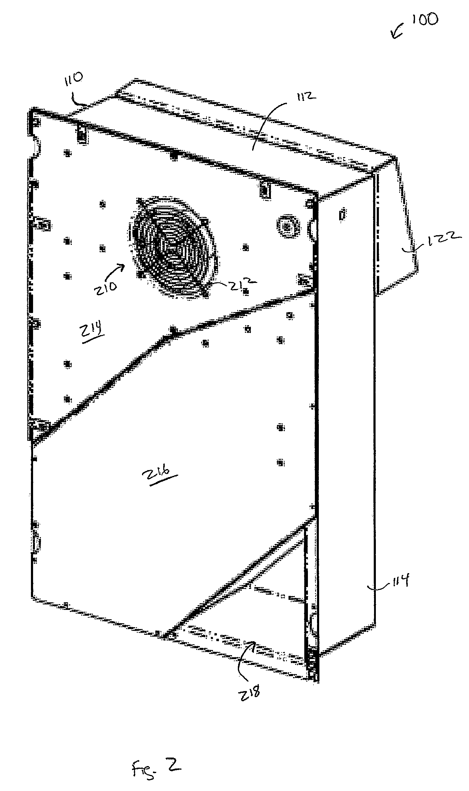
[0020]The following description describes embodiments of a heat exchanger to provide additional cooling capacity, and may be particularly well suited for outdoor equipment enclosures (also referred to as equipment cabinets). Generally, the equipment enclosures typically contain some form of electronic equipment and are typically sealed to prevent water and dust intrusion. The heat exchangers in accordance with embodiments of the present invention utilize two independent air-flow loops, one air-flow loop is for the ‘wet side’ that circulates air from the outside and the other ...


PUM


Abstract

A heat exchanger having a wet side separate from a dry side for an equipment cabinet is provided. The heat exchanger includes a heat exchanger enclosure having a wet side fan and a dry side fan. The wet side fan draws air in from the external environment and routes the air through a heat exchanger core and out the heat exchanger enclosure. The dry side fan draws air in from within the equipment cabinet and routes the air through the heat exchanger core and out back into the equipment cabinet. The air from the outside acts to cool the heat exchanger core, which in turn acts to cool the air from the dry side as the air is routed through the heat exchanger core.

Description

[0001]This application claims the benefit of U.S. Provisional Application No. 60 / 943,433, filed on Jun. 12, 2007, entitled “Heat Exchanger for Outdoor Enclosures”, which application is hereby incorporated herein by reference.TECHNICAL FIELD[0002]The present invention relates generally to thermal management and, more particularly, to a heat exchanger for cooling electronic equipment.BACKGROUND[0003]Electronic equipment frequently generates heat during operation and requires cooling in order to prevent the electronic equipment from over-heating and possibly failing. One common type of cooling involves the use of fans arranged so as to force the circulation of air from the outside around the electronic equipment. In this process, hot air from the inside is replaced with cooler air from the outside. The cooler air from the outside is circulated around the electronic equipment, thereby cooling the electronic equipment.[0004]One problem with this approach is that the outside air may be co...

Claims


Application Information

Patent Timeline
Patent Type & Authority Patents(United States)
IPC IPC(8): F24H3/06F28D15/00
CPCF28D9/00H05K7/206
Inventor FERNANDEZ, PEDRO A.
Owner ASYMBLIX
Why Eureka
Try Eureka