Expandable vertebral implant

a vertebral implant and expandable technology, applied in the field of expandable vertebral implants, can solve the problems of several challenges in spine surgery procedures

Active Publication Date: 2013-11-26
GLOBUS MEDICAL INC
View PDF17 Cites 138 Cited by
  • Summary
  • Abstract
  • Description
  • Claims
  • Application Information

AI Technical Summary

Problems solved by technology

Spinal surgery procedures can present several challenges because of the small clearances around the prosthetic when it is being inserted into position.

Method used


Image

  • Expandable vertebral implant
  • Expandable vertebral implant
  • Expandable vertebral implant

Examples


Embodiment Construction

[0043]The preferred embodiments of the invention will now be described with reference to the attached drawing figures. The following detailed description of the invention is not intended to be illustrative of all embodiments. In describing preferred embodiments of the present invention, specific terminology is employed for the sake of clarity. However, the invention is not intended to be limited to the specific terminology so selected. It is to be understood that each specific element includes all technical equivalents that operate in a similar manner to accomplish a similar purpose.

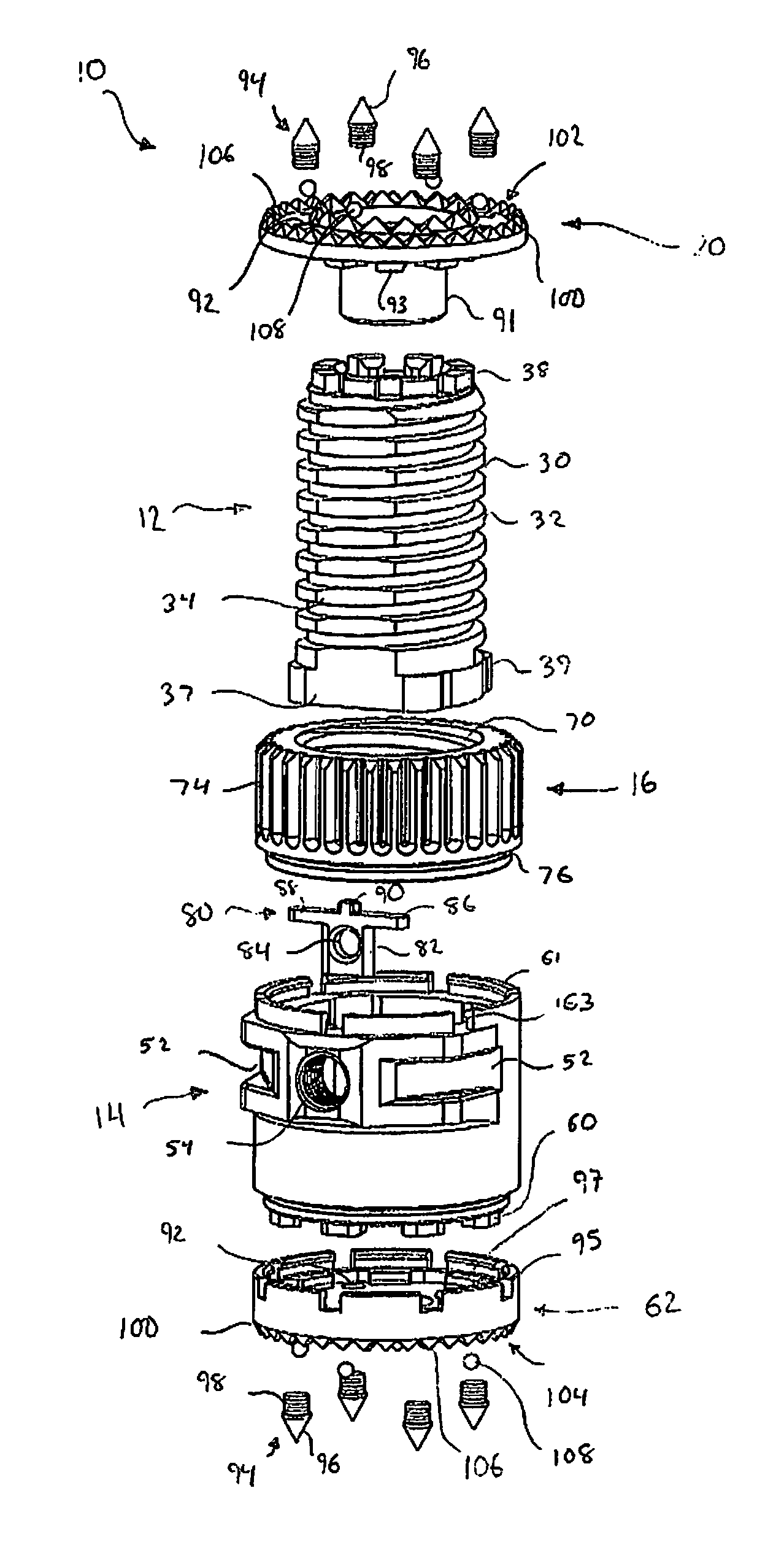
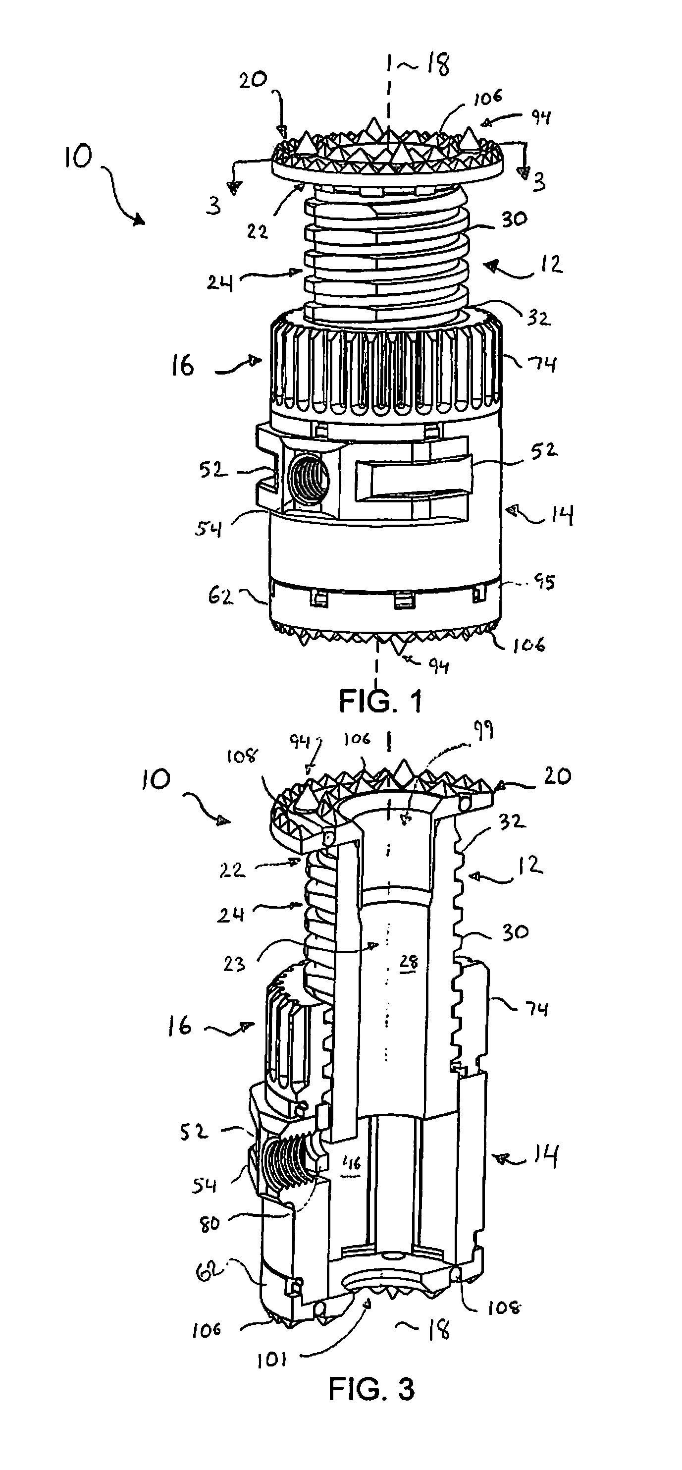
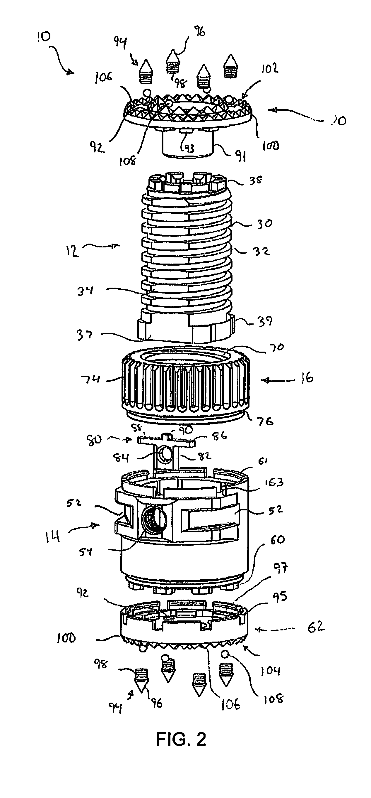
[0044]Referring to FIGS. 1-6, a preferred embodiment of an expandable vertebral implant 10 is shown. The implant 10 preferably comprises an inner member 12 which may be telescopingly received within an outer member 14. The implant 10 further comprises a gear member 16 generally configured to effect translation of the inner member 12 with respect to the outer member 14 thereby allowing for expansion and c...


PUM


Abstract

The present invention relates to an expandable implant for engagement between vertebrae generally comprising an inner member, outer member, and gear member positioned coaxial with respect to each other such that the inner and outer members are moveable relative to each other along an axis. The gear member is axially fixed to the outer member and freely rotatable with respect to the outer member and the gear member threadedly engages a threaded portion of the inner member to translate inner member along the axis. The implant is configured to engage the vertebrae in a predetermined alignment and the gear member includes gear teeth exposed to the exterior and configured to be accessible by a tool member at a plurality of angular positions around the perimeter of the implant device.

Description

CROSS-REFERENCE TO RELATED APPLICATIONS[0001]This application is a continuation-in-part of U.S. patent application Ser. No. 12 / 758,529 entitled “Expandable Vertebral Implant,” filed on Apr. 12, 2010 now U.S. Pat. No. 8,282,683, the entire disclosure of which is incorporated herein by reference.FIELD OF THE INVENTION[0002]The present invention relates to a device to support the spine after removal of at least a part of a vertebra.BACKGROUND OF THE INVENTION[0003]When a vertebra is damaged or diseased, surgery may be used to replace the vertebra or a portion thereof with a prosthetic device to restore spinal column support. For example, vertebral body replacement is commonly required in the treatment of vertebral fracture, tumor, or infection.[0004]In recent years, several artificial materials and implants have been developed to replace the vertebral body, such as, for example, titanium cages, ceramic, ceramic / glass, plastic or PEEK, and carbon fiber spacers. Recently, various expanda...

Claims


Application Information

Patent Timeline
Patent Type & Authority Patents(United States)
IPC IPC(8): A61F2/44
CPCA61F2/44A61F2/4455A61F2/4465A61F2/4611A61F2002/3008A61F2002/30383A61F2002/30393A61F2002/30395A61F2002/30495A61F2002/305A61F2002/30523A61F2002/3055A61F2002/30571A61F2002/30578A61F2002/30579A61F2002/30601A61F2002/30604A61F2002/3071A61F2002/30828A61F2002/30843A61F2002/4625A61F2002/4627A61F2002/4629A61F2310/00011A61F2310/00023A61F2310/00131A61F2002/30477A61F2002/30505A61F2002/30507A61F2002/30594A61F2002/30845A61F2002/30593A61F2/442
Inventor MCLAUGHLIN, COLMGRAY, JASONHIMMELBERGER, JAMESSHINN, THOMASADAMS, MARK
Owner GLOBUS MEDICAL INC
Why Eureka
Try Eureka