Feed device with improved envelope separation

a feed device and envelope technology, applied in the field of mail handling, can solve the problems of ineffective solution, device is unsatisfactory, and difficult to separate the first mailpi

Active Publication Date: 2013-11-26
NEOPOST TECH SA
View PDF11 Cites 0 Cited by
  • Summary
  • Abstract
  • Description
  • Claims
  • Application Information

AI Technical Summary

Benefits of technology

[0007]An object of the present invention is thus, essentially, to mitigate the above-mentioned drawback by proposing a mailpiece feed device that is particularly reliable and that makes it possible for the mailpieces to be separated effectively one-by-one. Another object of the invention is to minimize the structural changes that need to be made to conventional feed devices.
[0008]These objects are achieved by a mailpiece feed device designed to be mounted upstream from a franking machine, and comprising at least a mailpiece feed zone for receiving a stack of mailpieces of various formats supported by a first plurality of drive rollers and a separation zone for individually selecting the mailpieces and having a second plurality of drive rollers, at least first clutch means being provided for actuating said first plurality of drive rollers, wherein said mailpiece feed device further comprises at least one sensor for detecting passage of said mailpieces as they enter said separation zone, and control means for subjecting said first clutch means to forced deactivation followed by an activation / deactivation series so long as the sensor CN is not activated, so as to cause a rapid succession of horizontal movements generating jerky motion on said stack, conducive to facilitating mutual separation of said mailpieces.
[0009]By means of this specific structure that requires merely a sensor at the inlet of the separation zone, and appropriate control of clutching, it is simple to manage separation of the mailpieces by acting merely on the drive rollers of the feed zone.
[0013]The invention also provides a control method of controlling clutch means for actuating drive rollers supporting a stack of mailpieces of various formats at a feed zone of a mailpiece feed device designed to be mounted upstream from a franking machine, the control being performed as a function of the state of a sensor CN designed to detect passage of said mailpieces as they enter a separation zone that individually selects the mailpieces at the outlet of said feed zone, said control method consisting in subjecting said clutch means to forced deactivation followed by an activation / deactivation series so long as said sensor CN is not activated, so as to cause a rapid succession of horizontal movements generating jerky motion on said stack, conducive to facilitating mutual separation of said mailpieces.
[0014]Said activation / deactivation series of said clutch means may comprise a first activation / deactivation series that is of short duration, followed by a second activation / deactivation series that is of longer duration, and by a third activation / deactivation series that is also of longer duration.

Problems solved by technology

Unfortunately, the size of the stack of mailpieces and thus its weight has a considerable influence on ease of unstacking, because when the stack is heavy it is very difficult to separate the first mailpieces from the following mailpieces under the stack of mailpieces.
However, that solution is ineffective when loss of grip occurs between the rollers and the stack of mailpieces that they support.
However, in practice, that device is unsatisfactory because the jerky vertical movement does not change the extent to which the various mailpieces in the stack stick together, but on the contrary it does reduce the grip between the drive rollers and the first mailpiece in the stack.

Method used


Image

  • Feed device with improved envelope separation
  • Feed device with improved envelope separation
  • Feed device with improved envelope separation

Examples


Embodiment Construction

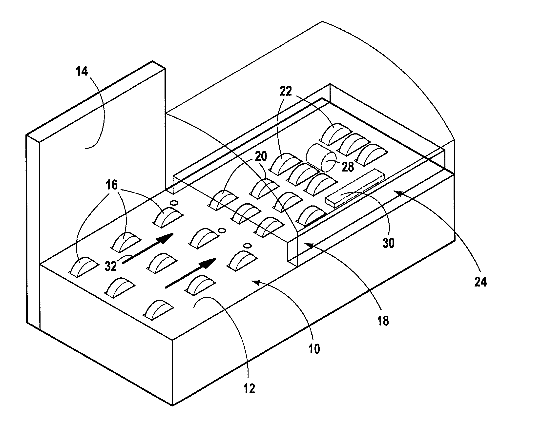
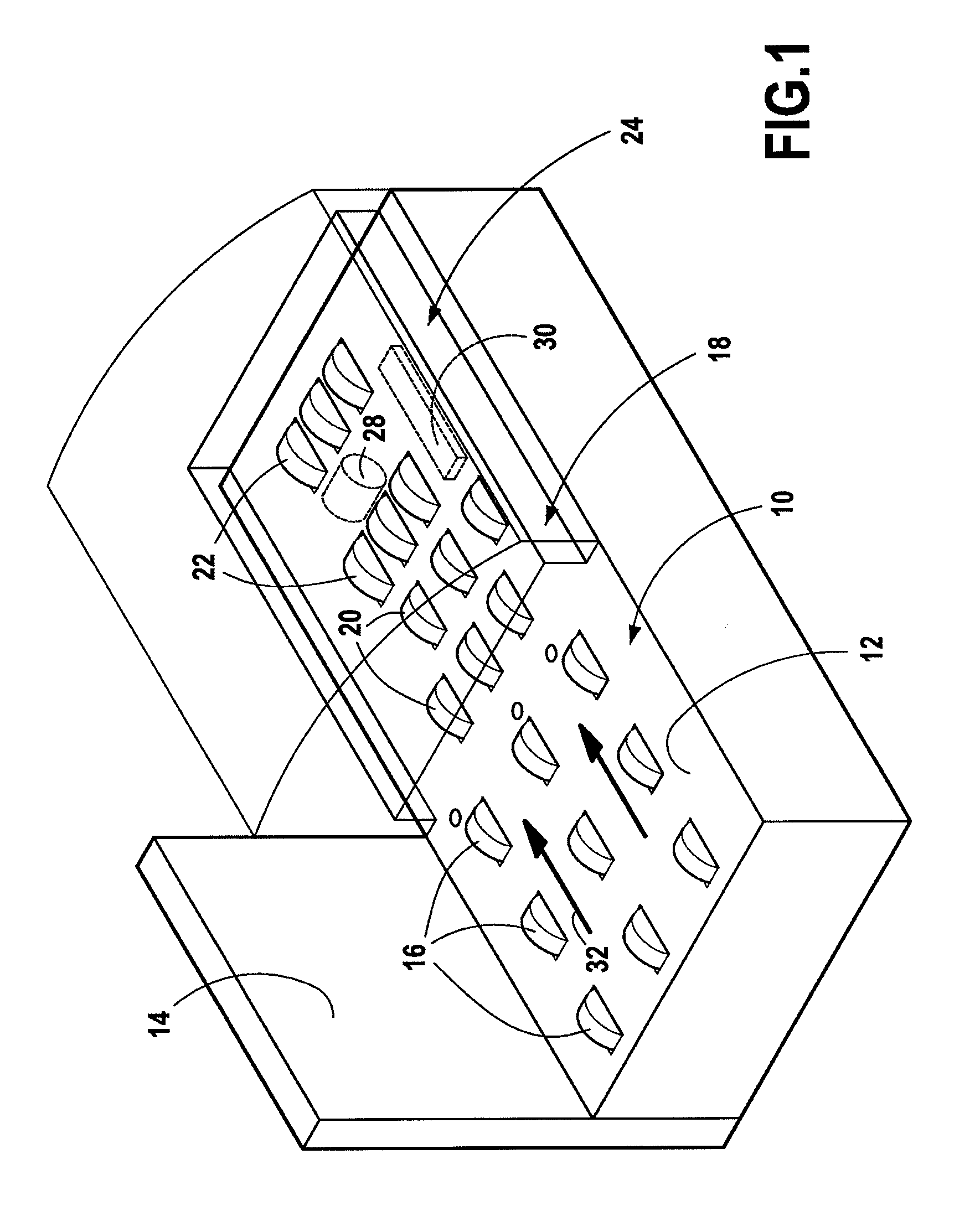
[0021]The automatic mailpiece feed device of FIG. 1 has a feed zone 10 made up essentially of a mailpiece-receiving deck 12, and of a longitudinal referencing wall 14, and designed to receive a stack of mailpieces dumped as they come (i.e. as a stack of mixed mail) and thus that can be of various sizes and weights. This zone is provided with conveyor means having a first plurality of drive rollers 16 making it possible to move the mailpieces downstream to a separation zone 18 provided with selector means made up of a presser and of a guide (that are not shown) co-operating with a second plurality of drive rollers 20, and from which the mailpieces are extracted individually from the stack. Finally, superposed conveyor means including a third plurality of drive rollers 22 (the associated upper idler rollers are not shown) are provided in a conveying zone 24 at the outlet of said separation zone so as to transfer the mailpieces extracted one-by-one in this way to the franking machine t...


PUM

PropertyMeasurementUnit
stop timeaaaaaaaaaa
timeaaaaaaaaaa
speedaaaaaaaaaa

Abstract

A mailpiece feed device designed to be mounted upstream from a franking machine, and comprising at least a mailpiece feed zone for receiving a stack of mailpieces of various formats supported by a first plurality of drive rollers and a separation zone for individually selecting the mailpieces and having a second plurality of drive rollers, at least first clutch means E3 being provided for actuating said first plurality of drive rollers, said mailpiece feed device further comprising at least one sensor CN for detecting passage of said mailpieces as they enter said separation zone, and control means for subjecting said first clutch means to forced deactivation followed by an activation / deactivation series so long as the sensor CN is not activated, so as to cause a rapid succession of horizontal movements generating jerky motion on said stack, conducive to facilitating mutual separation of said mailpieces.

Description

TECHNICAL FIELD[0001]The present invention relates exclusively to the field of mail handling and it relates more particularly to a feed device for feeding mailpieces to a franking machine, which feed device procures improved mailpiece separation.PRIOR ART[0002]Conventionally, a franking machine or “postage meter” must be adapted to receive various types of mailpiece such as documents, letters, or envelopes of various sizes. For this purpose, it is provided, often upstream from it, with an automatic feed device making it possible, in particular to convey such mailpieces at throughput rates suitable for enabling them to be processed by the franking machine. Such an automatic feed device or “feeder” has a deck for receiving a stack of mailpieces of various sizes, and it usually has means for stacking, separating, conveying, and optionally closing the mailpieces that are then processed by the franking machine.[0003]The unstacker means that are constituted by motor-driven drive rollers s...

Claims


Application Information

Patent Timeline
Patent Type & Authority Patents(United States)
IPC IPC(8): B65G59/00
CPCB65H1/06B65H3/063B65H3/60B65H7/18B65H2301/4493B65H2403/72B65H2511/414B65H2511/51B65H2513/512B65H2513/514B65H2553/412B65H2701/1916B65H2220/01B65H2220/09B65H2220/02
Inventor MAZEILLER, DOMINIQUE
Owner NEOPOST TECH SA
Why Eureka
Try Eureka