Magnetocaloric thermal generator having hot and cold circuits channeled between stacked thermal elements

a thermal generator and magnetocaloric technology, applied in the direction of energy-efficient heating/cooling, machines using electric/magnetic effects, machine operation mode, etc., can solve the problems of difficult industrialisation, high cost, and inconvenient use,

Inactive Publication Date: 2013-12-03
COOLTECH APPL SAS
View PDF14 Cites 7 Cited by
  • Summary
  • Abstract
  • Description
  • Claims
  • Application Information

AI Technical Summary

Benefits of technology

[0005]The present invention attempts to overcome these disadvantages by proposing a magneto-calorific thermal generator which is compact and multi-purpose, has high energy efficiency and a maximal transfer coefficient, while being easy to industrialise at reasonable cost and having a modular configuration enabling it to respond to a wide range of both industrial and domestic applications.
[0007]This staged construction allows the creation of thermal sub-assemblies, so-called thermal modules, possessing parallel channels, these thermal modules being connectable together in series and / or in parallel. This construction enables the number of stacked thermal elements per thermal module to be varied according to the required rate of fluid flow, and the number of juxtaposed thermal modules to be varied according to the required temperature range, providing very great modularity.

Problems solved by technology

As a result this solution creates a high thermal inertia which considerably penalises the energy efficiency of the generator.
It presents, however, the disadvantage of being difficult to industrialise, very costly and of non-modular configuration.

Method used


Image

  • Magnetocaloric thermal generator having hot and cold circuits channeled between stacked thermal elements
  • Magnetocaloric thermal generator having hot and cold circuits channeled between stacked thermal elements
  • Magnetocaloric thermal generator having hot and cold circuits channeled between stacked thermal elements

Examples


Embodiment Construction

[0005]The present invention attempts to overcome these disadvantages by proposing a magneto-calorific thermal generator which is compact and multi-purpose, has high energy efficiency and a maximal transfer coefficient, while being easy to industrialise at reasonable cost and having a modular configuration enabling it to respond to a wide range of both industrial and domestic applications.

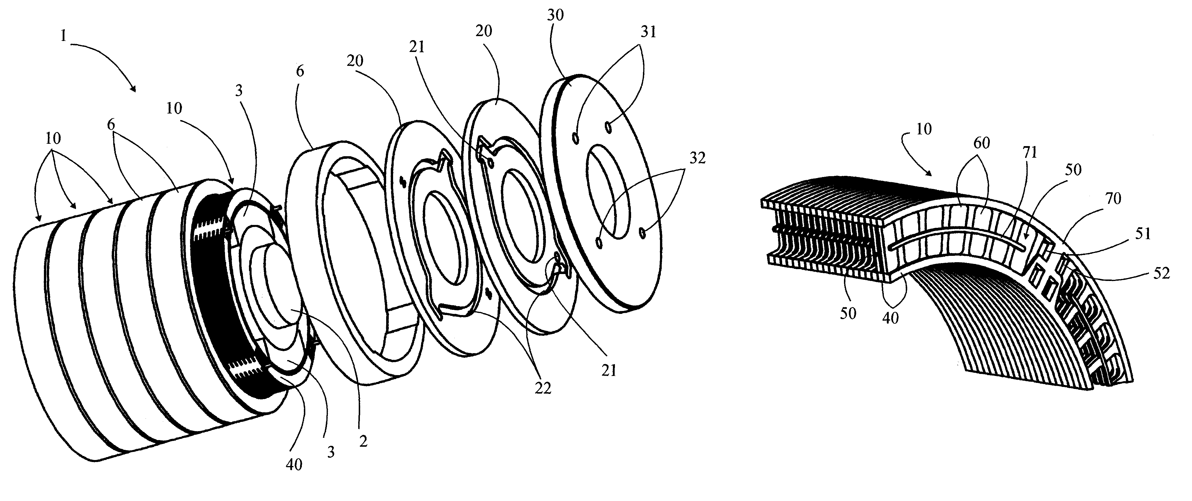
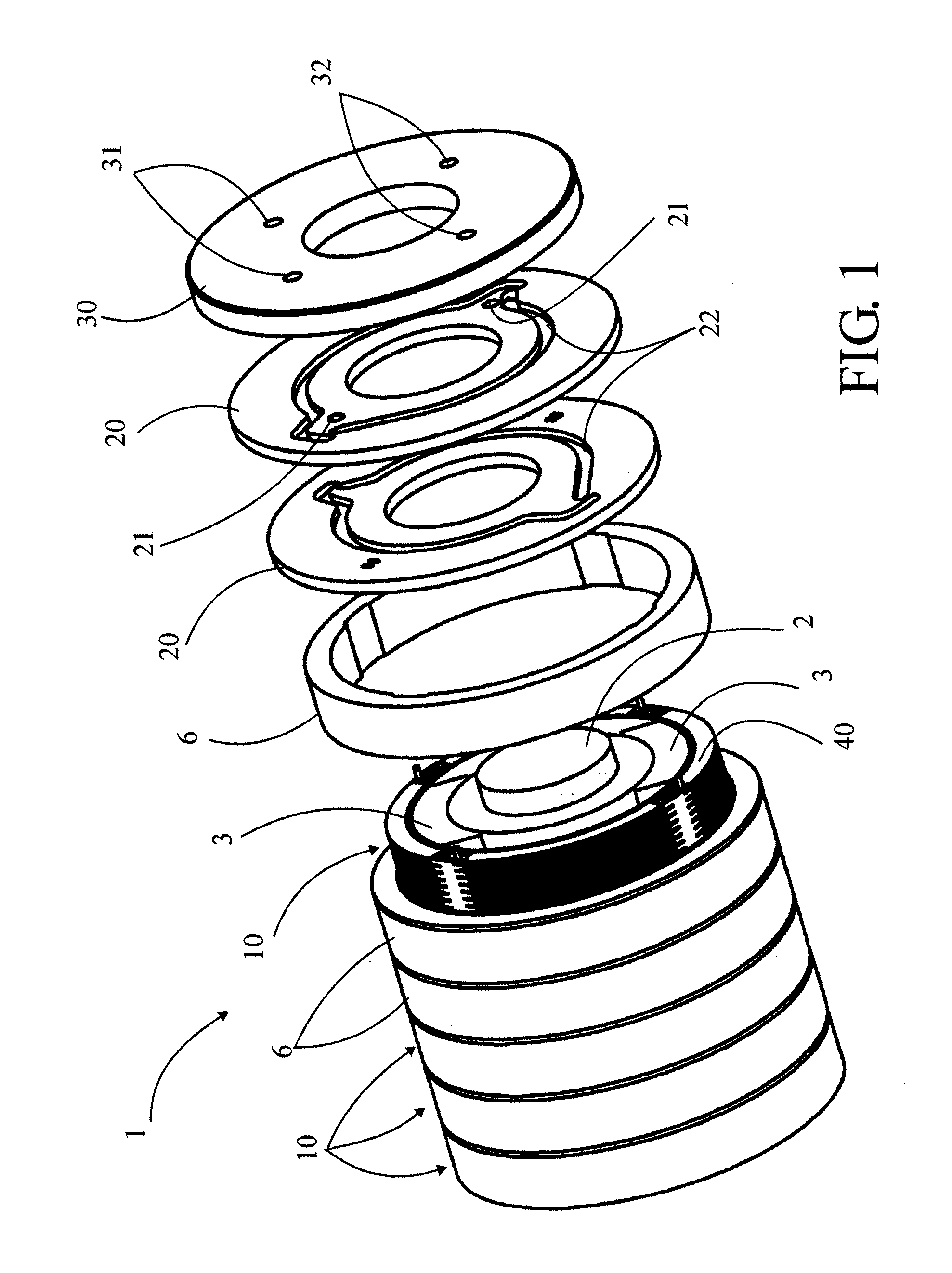
[0006]For this purpose, the invention concerns a thermal generator of the type mentioned in preamble, characterised in that it comprises at least one thermal module constituted from many thermal elements, stacked and arranged in order to delimit between each other channels for the circulation of heat transfer fluid, these channels being divided into hot channels in which the heat transfer fluid of the hot circuit flows and cold channels in which the heat transfer fluid of the cold circuit flows, and in that the said thermal elements have fluid inlet and outlet orifices which communicate with each ot...


PUM


Abstract

The thermal generator (1) which comprises at least one thermal module (10) constituted from many thermal elements (40), stacked and arranged in order to delimit channels therebetween for circulation of heat transfer fluid. These channels are divided into hot channels, in which the heat transfer fluid of the hot circuit flows, and cold channels, in which the heat transfer fluid of the cold circuit flows. The hot and cold channels are alternated between the thermal elements (40) and the thermal elements have fluid inlet and outlet orifices which communicate with one another so as to distribute the flow of heat transfer fluid of each hot and cold collector circuit, respectively, in the corresponding hot and cold channels.

Description

TECHNICAL FIELD[0001]The present invention concerns a magneto-calorific thermal generator comprising thermal elements based on magneto-calorific material, magnetic means arranged in order to create a variation in magnetic field in the said thermal elements and make their temperature vary, at least two separate collector circuits, a collector circuit referred to as “hot” and a collector circuit referred to as “cold”, in each of which circulates a separate heat transfer fluid arranged to collect respectively the calories and frigories emitted by the said thermal elements depending on their functional cycle, and means of connecting the said collector circuits to external circuits designed to use the said calories and frigories collected.PRIOR ART[0002]The new thermal generators which use the magneto-calorific effect of certain materials offer a very interesting ecological alternative to the conventional generators which are destined to disappear in a context of sustainable development ...

Claims


Application Information

Patent Timeline
Patent Type & Authority Patents(United States)
IPC IPC(8): F25B21/00
CPCF25B21/00Y02B30/66F25B2321/0023F25B2321/0022Y02B30/00
Inventor MULLER, CHRISTIANDUPIN, JEAN-LOUISHEITZLER, JEAN-CLAUDENIKLY, GEORGES
Owner COOLTECH APPL SAS
Why Eureka
Try Eureka