Plug movable to a plurality of positions depending upon characteristics of a load device

a technology of load device and plurality of positions, which is applied in the direction of flexible/turnable line connector, coupling device connection, electric discharge lamp, etc., can solve the problems of reducing the mobility of the device and difficult transportation

Inactive Publication Date: 2013-12-03
DET INT HLDG LTD
View PDF12 Cites 5 Cited by
  • Summary
  • Abstract
  • Description
  • Claims
  • Application Information

AI Technical Summary

Benefits of technology

[0002]While Power Supply Units (PSU) are becoming more flexible and more intelligent, the mobile devices that are powered up by them are diversifying a lot, having different characteristic. Each consumer device is coming with its own PSU, which makes transportation difficult and reduces the mobility of the devices.
[0011]In one of the exemplary embodiments, the cable plug comprises a locator drum, a locator tube disposed within the locator drum. The locator tube is selectively engaged with the locator drum so as to be moveable with the locator drum and is selectively disengaged with the locator drum so as to be moveable relative to the locator tube. A locking mechanism can be selectively engaged with and disengaged from the locator drum, and a pin assembly is located partially inside the locking mechanism and partly inside the locator tube and locator drum. The pin assembly is oriented to establish a circuit connection with selected mating connector(s) (signal pins) of the socket when the cable plug is in a selected position relative to the socket. Positive and ground circuit connection are maintained, irrespective of the relative position of the socket and cable plug, and the pin assembly is configured, so that relative movement of the cable plug relative to the socket enables selection of the selector pin(s) of the socket that will complete a circuit, while the other selector pins are isolated from the circuit.

Problems solved by technology

Each consumer device is coming with its own PSU, which makes transportation difficult and reduces the mobility of the devices.

Method used


Image

  • Plug movable to a plurality of positions depending upon characteristics of a load device
  • Plug movable to a plurality of positions depending upon characteristics of a load device
  • Plug movable to a plurality of positions depending upon characteristics of a load device

Examples


first embodiment

of the Socket-cable Plug System (FIGS. 3-9)

[0035]FIG. 3 presents a general view of the cable plug P for a first embodiment of the socket-cable plug system, providing in this example four selector positions (following the electrical function described in 2.).

[0036]FIG. 4 presents the same cable plug P with details regarding the selection of one of the four positions by rotating locator drum 1 against locking mechanism 6. Locator drum 1 features locking tabs that will be further locked into the receiving part of the socket S. Therefore rotating locking mechanism 6 in respect of locator drum 1 is equivalent with rotating locking mechanism 6 in respect of the receiving socket S. Locator drum 1 is constructed with a locking system against locking mechanism 6. The rotation between locator drum 1 and locking mechanism 6 is possible only when the locking system is disengaged by pushing it (pressed by finger). Hence a position between locator drum 1 and locking mechanism 6 can be changed onl...

second embodiment

of the Socket-cable Plug System (FIGS. 10-15)

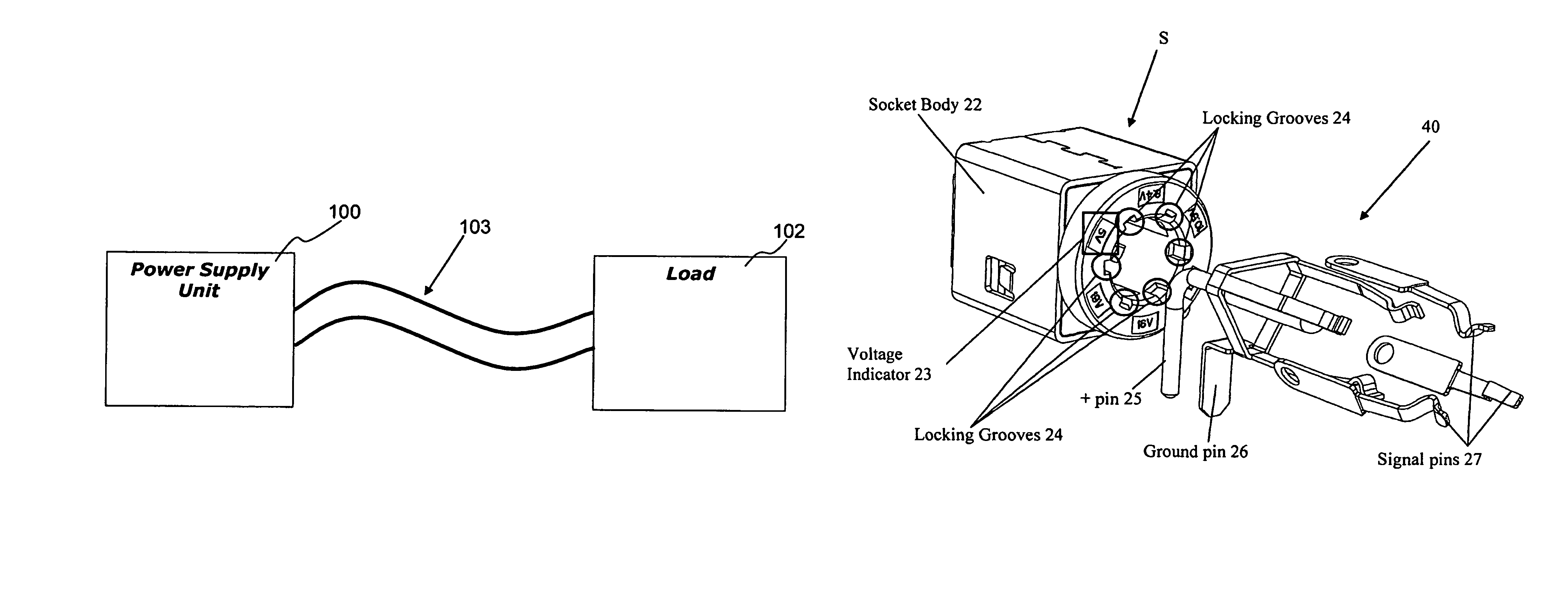
[0055]FIG. 10 shows the general view of the plug P of the second embodiment, which achieves the selection by having 180° of the negative end terminal of the plug P covered with insulation 17 in the area of contact with the signal pins of the socket. The three signal pins 27 of the pin assembly are placed inside of the socket body 22 at 120° from each other; therefore the non-insulated part of the negative end terminal of the plug P can touch one or two signal pins at a time, as presented in FIG. 15. FIG. 15 presents the general method of obtaining six positions selector using three contact pins 27—the six combinations are obtained by contacting one pin at a time or two pins at a time.

[0056]FIG. 11 shows the plug P of the second embodiment with details of the negative and terminal, positive end terminal and the 180° isolated area around the end of the negative terminal. The construction of the plug P for the second embodiment includes the ...


PUM


Abstract

A new and useful cable plug is provided, that is configured for a socket-plug system connecting a PSU to a load device over a 2 wire cable. The cable plug is selectively moveable to one of a plurality of positions for selecting a predetermined output voltage (or other operational characteristic) for the load device In addition, a new and useful socket is provided, that is configured to mate with the cable plug, to provide the selected output voltage (or other operational characteristic) for the load device.

Description

RELATED APPLICATION / CLAIM OF PRIORITY[0001]This application is related to and claims priority from provisional application Ser. No. 61 / 402,490, filed Aug. 31, 2010, which provisional application is incorporated by reference herein.INTRODUCTION[0002]While Power Supply Units (PSU) are becoming more flexible and more intelligent, the mobile devices that are powered up by them are diversifying a lot, having different characteristic. Each consumer device is coming with its own PSU, which makes transportation difficult and reduces the mobility of the devices.[0003]A universal PSU should be able to adapt its output characteristics to varied load devices requirements. Many today's PSU are already capable of such adaptation and their flexibility will increase in the future. However, the information regarding the load device characteristics have to be communicated to the PSU. Minimum human intervention should be involved in order to facilitate the characteristic selection.[0004]Usually a mini...

Claims


Application Information

Patent Timeline
Patent Type & Authority Patents(United States)
IPC IPC(8): H01R25/00
CPCH01R29/00H01R13/701H01R24/58H01R35/00H01R2103/00
Inventor BUCHERU, BOGDAN TUDORTHONGKHUMROL, PAIRORHUANG, JUI CHINGPOPESCU, CONSTANINVELASCO, JR., ENRIQUE H.
Owner DET INT HLDG LTD
Why Eureka
Try Eureka