Transporting apparatus and printer using the same

a technology of transporting equipment and printing machine, which is applied in the directions of transportation, packaging, thin material processing, etc., can solve the problems of poor relative position accuracy, denting of the medium, and affecting the transporting of the transporting medium, so as to improve the relative position accuracy

Active Publication Date: 2013-01-08
BROTHER KOGYO KK
View PDF4 Cites 2 Cited by
  • Summary
  • Abstract
  • Description
  • Claims
  • Application Information

AI Technical Summary

Benefits of technology

[0009]In the transporting apparatus having the curved portion as mentioned above, transporting the transporting medium assuredly by reducing an effect of a frictional force between the transporting medium and the curved portion by providing a pair of transporting rollers in the curved portion is considered. When the pair of transporting rollers is arranged in the curved portion, the transporting medium is guided to a nipping position which is located between the pair of transporting rollers, by the guiding portion of the movable member. However, in the guiding portion provided to the movable member, an accuracy of position with respect to the nipping position is poor (not favorable), and there is a possibility that the transporting medium hits the pair of transporting roller and is dented.
[0010]When the guiding portion is brought closer to the nipping position, it is possible to reduce a shift in position of the transporting medium which is transported and the nipping position. However, when the guiding portion is brought excessively closer to the nipping position, while the transporting medium passes through the pair of transporting rollers, the transporting medium bent in the curved portion is pressed strongly against the guiding portion, and the frictional force between the transporting medium and the guiding portion becomes substantial, thereby hindering the transporting of the transporting medium and leaving a scratch on a surface of the transporting medium by the guiding portion.
[0012]The present invention has been made in view of the abovementioned problems, and an object of the present invention is to provide a transporting apparatus in which it is possible to improve an accuracy of relative positions of the guiding portion provided to the movable member, and the nipping position of the pair of transporting rollers.
[0019]The guiding portion is positioned with respect to the shaft of the drive roller by the positioning portion. Therefore, it is possible to improve an accuracy of relative positions of the guiding portion and the nipping position of the pair of transporting rollers. As a result, it is possible to realize a transporting apparatus which is capable of transporting the transporting medium with normalcy even when a radius of curvature of the curved portion is made small, and a transporting apparatus which is capable of transporting the transporting medium with normalcy irrespective of the type of the transporting medium.
[0024]According to the present invention, it is possible to improve an accuracy of relative positions of the nipping position of the pair of transporting rollers and the guiding portion provided to the movable member, and it is possible to prevent the recording medium from hitting against the transporting roller, and from pressing hard against the guiding portion.

Problems solved by technology

However, in the guiding portion provided to the movable member, an accuracy of position with respect to the nipping position is poor (not favorable), and there is a possibility that the transporting medium hits the pair of transporting roller and is dented.
However, when the guiding portion is brought excessively closer to the nipping position, while the transporting medium passes through the pair of transporting rollers, the transporting medium bent in the curved portion is pressed strongly against the guiding portion, and the frictional force between the transporting medium and the guiding portion becomes substantial, thereby hindering the transporting of the transporting medium and leaving a scratch on a surface of the transporting medium by the guiding portion.
As it has been described above, when the pair of transporting rollers is provided at an upstream side of the curved portion in the transporting apparatus having the guiding portion provided to the movable member, which forms an outer side of the curved portion, due to poor accuracy of relative positions of the guiding portion and the nipping position of the pair of transporting rollers, hindering of transportation of the transporting medium is anticipated.

Method used


Image

  • Transporting apparatus and printer using the same
  • Transporting apparatus and printer using the same
  • Transporting apparatus and printer using the same

Examples


first modified embodiment

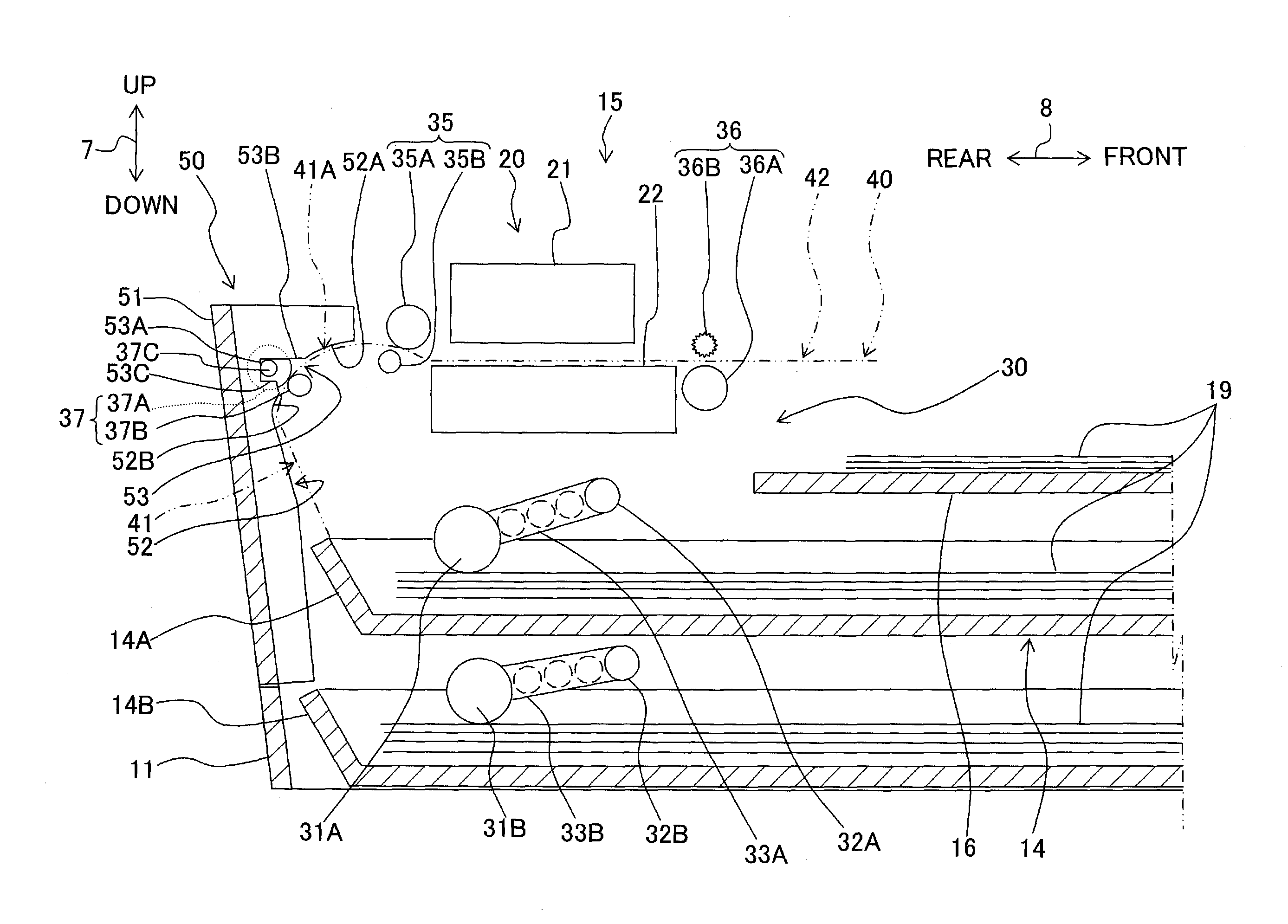
[0080]An arrangement in which the movable member 50 is positioned by the engaging portion 54 and the notch 53 has been described above. However, in a first modified embodiment, an arrangement in which the movable member 50 is positioned by an engaging portion 55 as shown in FIG. 7 instead of the engaging portion 54 and the notch 53 will be described. The engaging portion 55 is formed to be C-shaped with a part of a ring notched out, and is provided at a position at which the shaft 37C is press-fitted when the attitude of the movable member 50 changes from the second attitude to the first attitude.

[0081]The engaging portion 55 positions the movable member 50 with respect to the shaft 37C when the peripheral surface of the shaft 37C makes a contact with an inner peripheral surface. Then the engaging portion 55 latches the movable member 50 with the shaft 37C. The rotatable shaft 37C makes a sliding contact with the inner peripheral surface of the engaging portion 55. In other words, t...

second modified embodiment

[0082]An arrangement in which the claw portion 54B is hitched on the shaft 37C by the snap-fit has been described above. However, an arrangement in which the claw portion 54B is movably supported in the vertical direction 7 by using an elastic member such as a coil spring or a plate spring shown in FIG. 8, and the claw portion 54B is hitched on the shaft 37C may be used.

[0083]In FIG. 8, the claw portion 54B is fixed to the other end of the plate spring 57 of which one end is fixed to the base portion 51 of the movable member 50, and is supported by the plate spring 57 to be movable in the vertical direction 7 in the first attitude, and also is biased upward in the first attitude. The plate spring 57 and the claw portion 54B correspond to the deformable portion of the present teaching.

[0084]In the embodiment and the modified embodiments described above, the transporting medium 19 which is transported in a substantially vertical direction is directed in a substantially horizontal dire...


PUM


Abstract

There is provided a transporting apparatus which includes a pair of transporting rollers including drive and driven rollers; a transporting path including a curved portion which changes a transporting direction of the transporting medium; a movable member which is changeable to a first attitude forming an outer side of the curved portion to guide the transporting medium, and a second attitude opening the curved portion not to form the outer side of the curved portion. The movable member has a guiding portion which guides the transporting medium between the pair of transporting rollers, in the first attitude, and a positioning portion which positions the guiding portion with respect to a shaft of the drive roller in the first attitude, and which is separated from the shaft of the drive roller in the second attitude.

Description

CROSS REFERENCE TO RELATED APPLICATION[0001]The present application claims priority from Japanese Patent Application No. 2010-125226, filed on May 31, 2010, the disclosure of which is incorporated herein by reference in its entirety.BACKGROUND OF THE INVENTION[0002]1. Field of the Invention[0003]The present invention relates to a transporting apparatus in which a guiding portion which guides a medium to be transported (hereinafter, ‘transporting medium’) between a pair of transporting rollers which transports by pinching the sheet shaped transporting medium is provided to a movable member, and a printer using the transporting apparatus.[0004]2. Description of the Related Art[0005]A transporting apparatus which includes a pair of transporting rollers which transports by pinching a sheet shaped transporting medium such as a recording paper, a card, and a sealed cover, and a transporting path through which the transporting medium passes, has hitherto been provided. The transporting app...

Claims


Application Information

Patent Timeline
Patent Type & Authority Patents(United States)
IPC IPC(8): B41J2/01
CPCB65H5/062B65H5/38B65H2402/46B65H2801/06B65H2404/143B65H2404/6111B65H2601/11B65H2402/5152B65H2402/51
Inventor UCHINO, YUTA
Owner BROTHER KOGYO KK
Why Eureka
Try Eureka