Spindle motor and disk drive apparatus

a disk drive and spindle technology, applied in the direction of magnetic recording, data recording, instruments, etc., can solve the problem of further reducing the thickness of the motor mounted in the disk drive apparatus, and achieve the effect of shortening the startup time and sufficient torqu

Active Publication Date: 2013-12-03
NIPPON DENSAN CORP
View PDF17 Cites 10 Cited by
  • Summary
  • Abstract
  • Description
  • Claims
  • Application Information

AI Technical Summary

Benefits of technology

[0008]According to various preferred embodiments of the invention, it is possibl

Problems solved by technology

However, in recent years, as thinner disk drive apparatuses are demanded, it is neces

Method used


Image

  • Spindle motor and disk drive apparatus
  • Spindle motor and disk drive apparatus
  • Spindle motor and disk drive apparatus

Examples


Embodiment Construction

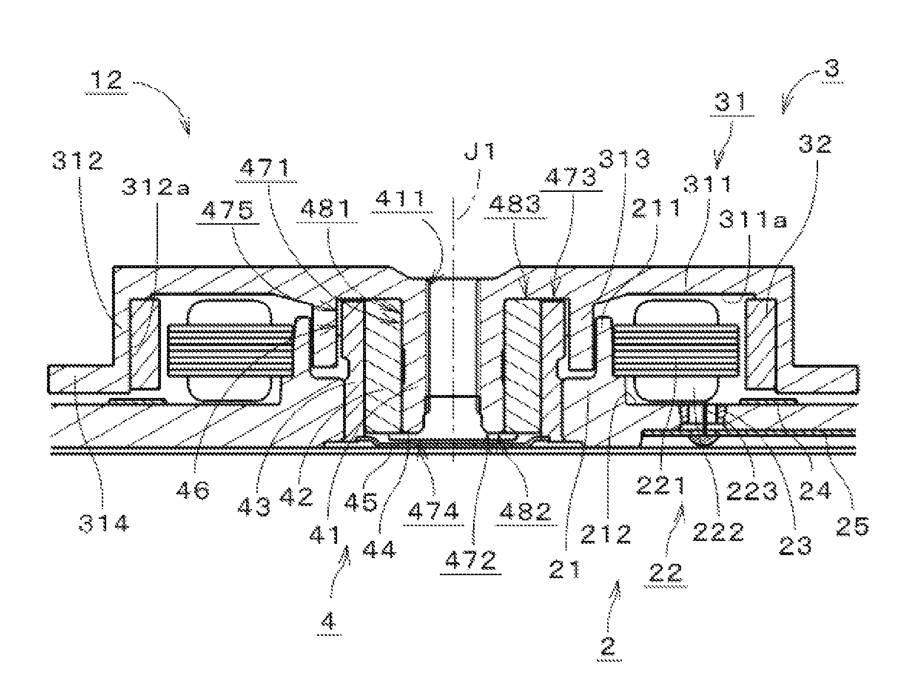
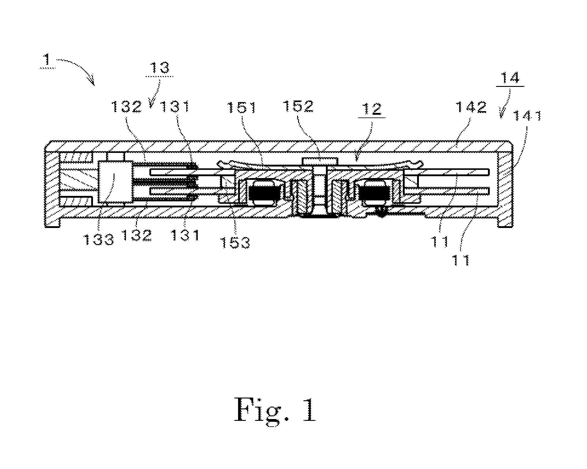
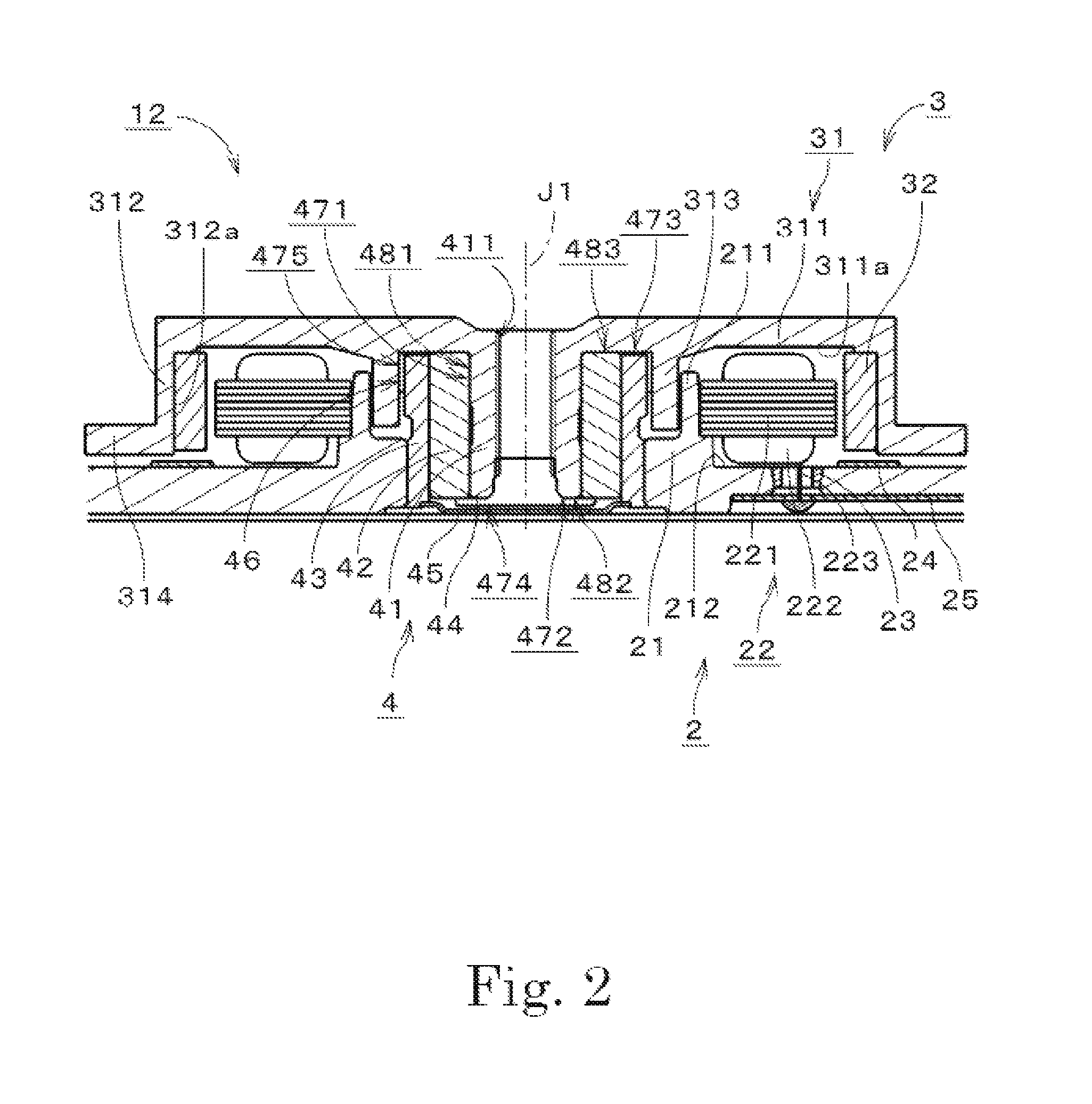
[0038]In the following description, an upper side of a motor in a central axis direction thereof in FIG. 1 is simply referred to as an “upper side”, and a lower side thereof is simply referred to as a “lower side”. A vertical direction does not represent a positional relationship or a direction when being assembled in an actual device. Further, a direction parallel or substantially parallel to a central axis is referred to as an “axial direction”, a direction that is orthogonal or substantially orthogonal to the central axis with reference to the central axis is simply referred to as a “radial direction”, and a circumferential direction with reference to the central axis is simply referred to as a “circumferential direction”.

[0039]Further, in the following description, the “parallel” direction includes both a parallel and an approximately parallel direction. Further, in the following description, the “orthogonal” direction includes both an orthogonal and an approximately orthogonal ...


PUM


Abstract

A spindle motor of a disk drive apparatus includes a base unit, a stator, a covered cylindrical rotor hub, a rotor magnet, and a bearing mechanism. The rotor magnet is an Nd—Fe—B bond magnet. The thickness of the rotor magnet in the radial direction is about 0.7 mm or more and about 1.0 mm or less. The distance between the rotor magnet and the stator core in the radial direction is about 0.15 mm or more and about 0.20 mm or less. A torque constant Kt of torque generated between the stator and the rotor magnet is about 4 mN·m/A or more and about 6 mN·m/A or less. A motor constant Km is about 2 mN·m/(A·√Ω) or more and about 4 mN·m/(A·√Ω) or less.

Description

BACKGROUND OF THE INVENTION[0001]1. Field of the Invention[0002]The present invention relates to a spindle motor and more specifically to a spindle motor for a disk drive apparatus.[0003]2. Description of the Related Art[0004]In the related art, a spindle motor (hereinafter, simply referred to as a “motor”) is mounted in a disk drive apparatus such as a hard disk drive. In an outer rotor-type motor disclosed in JP-A-2004-135467, a rotor set includes a rotating hub body of a cup shape and a drive magnet. A stator set includes a stator core and a drive coil wound on the stator core. The drive magnet of the motor disclosed in JPA-2004-135467 is fixed to an inner circumferential surface of an annular standing wall part of the rotating hub body, and faces an outer circumferential surface of the stator core. When the motor is driven, a magnetic action is generated between the drive magnet and the drive coil. Further, JP-A-2008-97803 discloses a motor in which a permanent magnet is dispose...

Claims


Application Information

Patent Timeline
IPC IPC(8): G11B19/20
CPCG11B19/2009
Inventor ABE, HIROYUKI
Owner NIPPON DENSAN CORP
Why Eureka
Try Eureka