
Driver of electric compressor

a technology of electric compressors and drive shafts, which is applied in the direction of motor/generator/converter stoppers, piston pumps, dynamo-electric converter control, etc., can solve the problems of compressors falling out of sync at the start, thermal load fluctuation in the compartment, and solar radiation, so as to reduce the advancement of winding current-phase, reduce torque fluctuation, and improve the effect of start performan

Active Publication Date: 2006-08-01
PANASONIC CORP
View PDF8 Cites 18 Cited by
  • Summary
  • Abstract
  • Description
  • Claims
  • Application Information

AI Technical Summary

Benefits of technology

"The present invention provides a compressor driver that can start under pressure difference and maintain stable operation. The driver has a unique structure that controls the current phase of the motor to generate sufficient torque to start the compressor. The driver can also decrease the current phase to prevent unstable operation. The driver can switch the dc voltage supplied to the motor to improve start-performance. The driver carries out switching with three-phase modulation to achieve a smooth current and improve start-performance. The compressor driver is mountable to a car air-conditioner to ensure positive operation in severe conditions."

Problems solved by technology

Since a vehicle travels frequently through a sunny place and shade, it is subject to solar radiation, and the thermal load in the compartment fluctuates frequently.
However, the methods of increasing only a starting voltage, a duty ratio, or a current threshold value for improving the start-performance under pressure difference involves increasing the current in a large amount at the same time.
However, when the pressure difference in the refrigerating cycle exceeds the certain level, an over-current protection is activated, so that the compressor cannot start.
The rotor fails in following the rotating magnetic field due to a large torque load, so that the compressor falls in out of sync. at the start.
Once the compressor falls in this state, a positional detection becomes unstable, which disables the compressor from starting.
During the waiting time, the temperature of the compartment rises in the condition of cooling operation, so that the crew and passengers feel uncomfortable.
The vehicle has a large area occupied by windows, so that it is subject to solar radiation and the thermal load frequently fluctuates in the compartment.
As a result, the crew and passengers feel much more uncomfortable.

Method used


Image

  • Driver of electric compressor
  • Driver of electric compressor
  • Driver of electric compressor

Examples


Embodiment Construction

Best Mode for Carrying out the Invention

[0051]A driver of a compressor mounted in a car air-conditioner in accordance with an exemplary embodiment of the present invention is demonstrated hereinafter with reference to the accompanying drawings.

Exemplary Embodiment

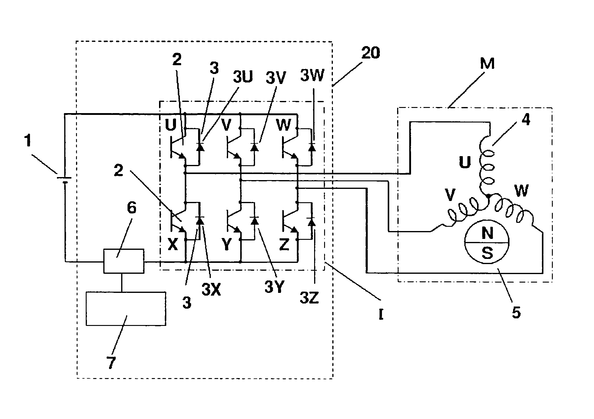
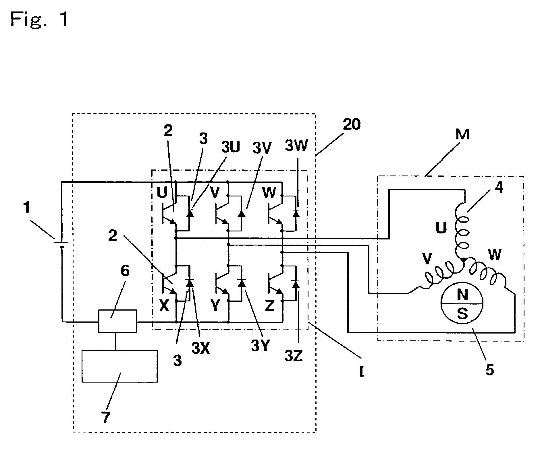
[0052]An electric circuit in accordance with the exemplary embodiment of the present invention is described with reference to FIG. 1, which shows a schematic circuit diagram of the compressor driver in accordance with the embodiment of the present invention.

[0053]In FIG. 1, inverter 20 is coupled with battery 1, i.e., a power supply, and sensor-less brush-less motor M (hereinafter referred to simply as a motor). Inverter 20 comprises the following elements:

[0054]inverter module I;

[0055]current sensor 6 for detecting a current necessary to drive motor M; and

[0056]control circuit 7 for controlling switching elements 2 based on signals supplied from current sensor 6.

Inverter module I includes the following elements:

[0057]plura...


PUM


Abstract

A compressor driver for a compressor is provided, wherein at the start of the compressor, a phase of the current flowing in the motor is controlled to be ahead of an induction voltage, then the advancement of the phase is controlled to decrease. Under an unstable condition to detect a position, such as at the start under pressure-difference, the foregoing control allows the phase to advance up to the current-phase where the max. torque can be produced, thereby drawing the instantaneous max. torque of the motor for starting the compressor. Then the control reduces the advancement for obtaining a stable operation.

Description

FIELD OF THE INVENTION[0001]The present invention relates to drivers of electric compressors to be used mainly in air-conditioners including a car air-conditioner.BACKGROUND OF THE INVENTION[0002]A car air-conditioner including an electric compressor (hereinafter referred to simply as a compressor) which employs a sensor-less dc brush-less motor as a driver, is disclosed in, e.g., Japanese Patented Publication No. JP06-156055. This air-conditioner is shown in FIG. 21 which illustrates a schematic structure of this conventional car air-conditioner including a compressor.[0003]In FIG. 21, air duct 101 sucks air from air inlet 103 due to an operation of indoor fan 102, and blows the air through indoor heat exchanger 104 into the compartment of the vehicle through air outlet 105. Heat exchanger 104 disposed in air-duct 101 forms a refrigerating cycle together with compressor 106 driven by a sensor-less dc brush-less motor, four-way switching valve 107 for selecting heating or cooling by...

Claims


Application Information

Patent Timeline
Patent Type & Authority Patents(United States)
IPC IPC(8): H02P23/00H02P25/00H02P27/00F04B49/06B60H1/32F04B35/04F04B49/20H02P6/06H02P6/08H02P23/03
CPCB60H1/3222B60H1/3226F04B35/04H02P23/03F04B49/20F04B2203/0201F04B2203/0202
Inventor YOSHIDA, MAKOTOGOTO, NAOMI
Owner PANASONIC CORP
Learn More