Efficient manual to automatic valve conversion device

a technology of automatic valve and conversion device, which is applied in the direction of valve details, valve arrangement, operating means/releasing devices, etc., can solve the problem that the installation cost may exceed the cost of the valve itself, and achieve the effect of saving battery life and being convenient and efficien

Inactive Publication Date: 2015-04-28
TAEUS CORP
View PDF40 Cites 19 Cited by
  • Summary
  • Abstract
  • Description
  • Claims
  • Application Information

AI Technical Summary

Benefits of technology

[0010]In yet another aspect of the invention there is provided a flexible anti-rotation structure or mechanism extended between the valve actuator or motor and a fixed rotational reference point such as a bracket mounted on the conduit or valve body or nearby wall or support structure, such that when the valve actuator or motor is properly mounted on and supported by the valve handle, the valve actuator and manual valve operate together as a powered valve regardless of the various type and operating position and range of shaft translation and rotation of the knob, handle or lever of the manual valve. This flexible, or less than rigid, connection of the anti-rotation coupling mechanism between the motor and the fixed anti-rotation reference point, which may operation in tension, compression, shear, bend, or any combination to resist motor counter rotation, also allows the valve actuator to tolerate a limited initial degree or of motor counter-rotation. Initial motor counter-rotation upon motor start is typically less than one quarter turn (90 degrees) in most installations and not more than one half turn (180 degrees) in any installation, before the anti-rotation coupling mechanism is fully effective, motor counter-rotation is fully arrested, and sufficient torque is available to operate the valve.
[0028]Motor torque may be preset or adjustable. Torque will typically be set to a maximum value greater than the maximum valve handle resistance to rotation and less than the valve stop structural limits, in order to avoid damage to the valve. The motor control circuit and actuator motor may provide for a simple on / off valve operation, rotating the valve handle from the open stop to the closed stop, or it may provide for adjustable flow control by timed or stepped range valve operation. Further, it may be incorporated into a process control loop using a sensor system and feedback signal for dynamic valve operation and flow control in the fluid conduit.

Problems solved by technology

The cost of installation may exceed the cost of the valve itself.

Method used


Image

  • Efficient manual to automatic valve conversion device
  • Efficient manual to automatic valve conversion device
  • Efficient manual to automatic valve conversion device

Examples


Embodiment Construction

[0036]The invention is susceptible of many embodiments and variations. What is described here is illustrative, but not limiting, of the scope of the invention.

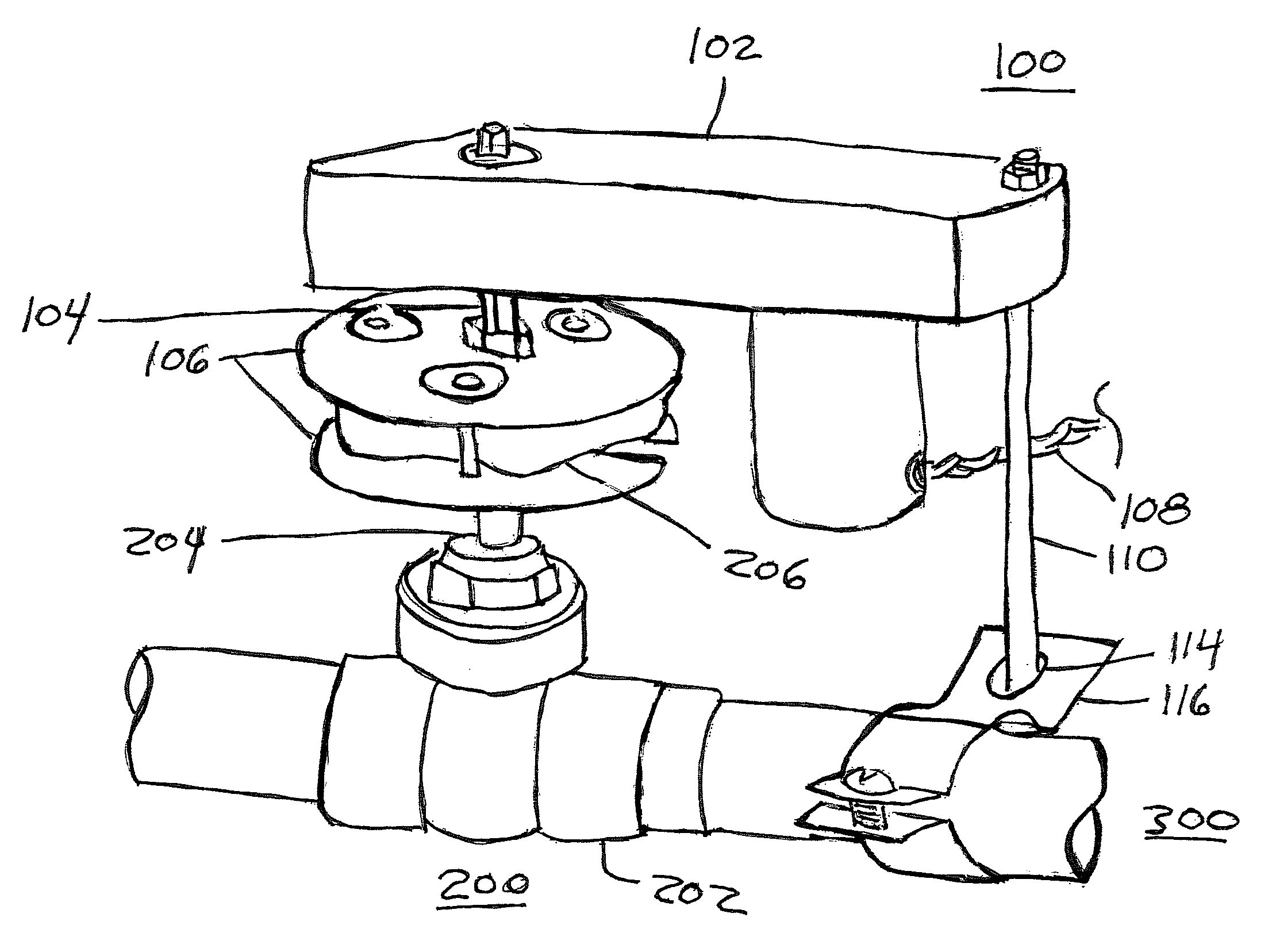
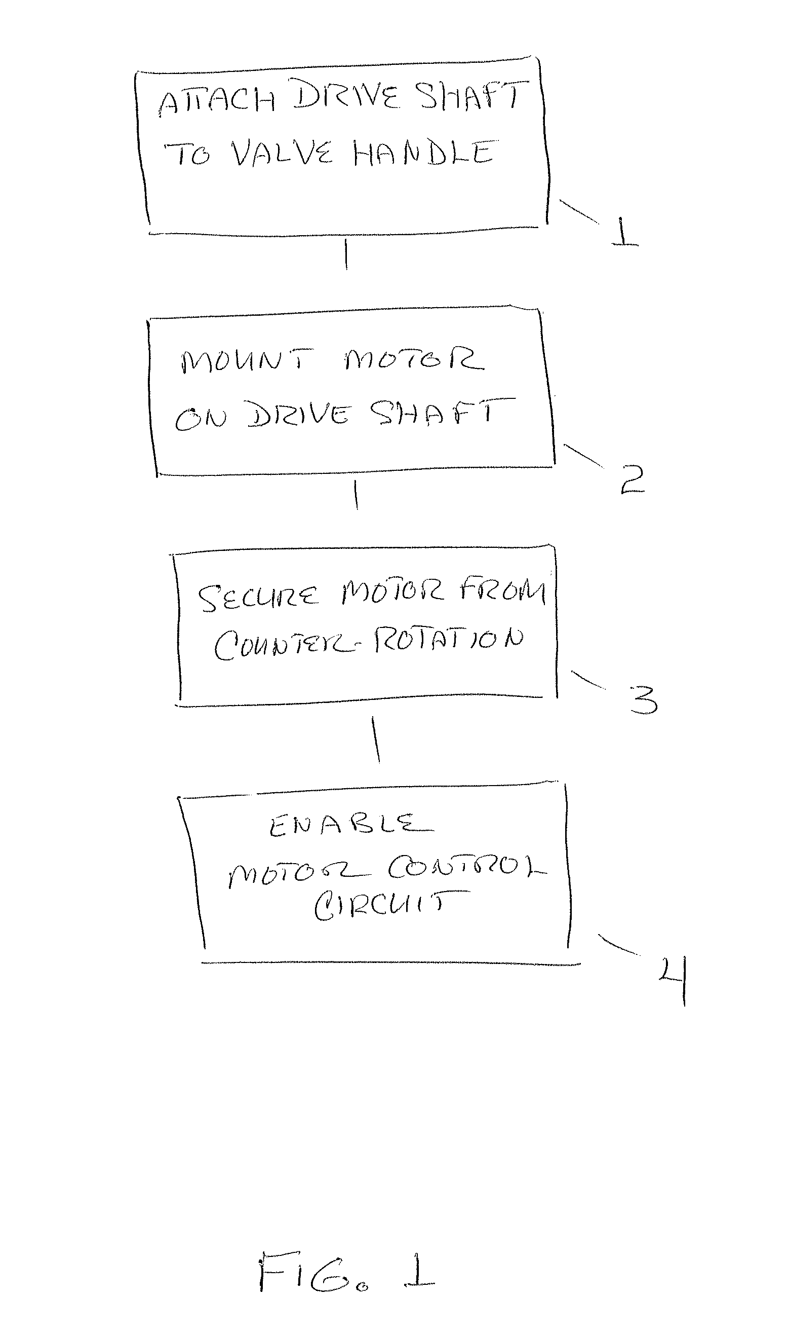
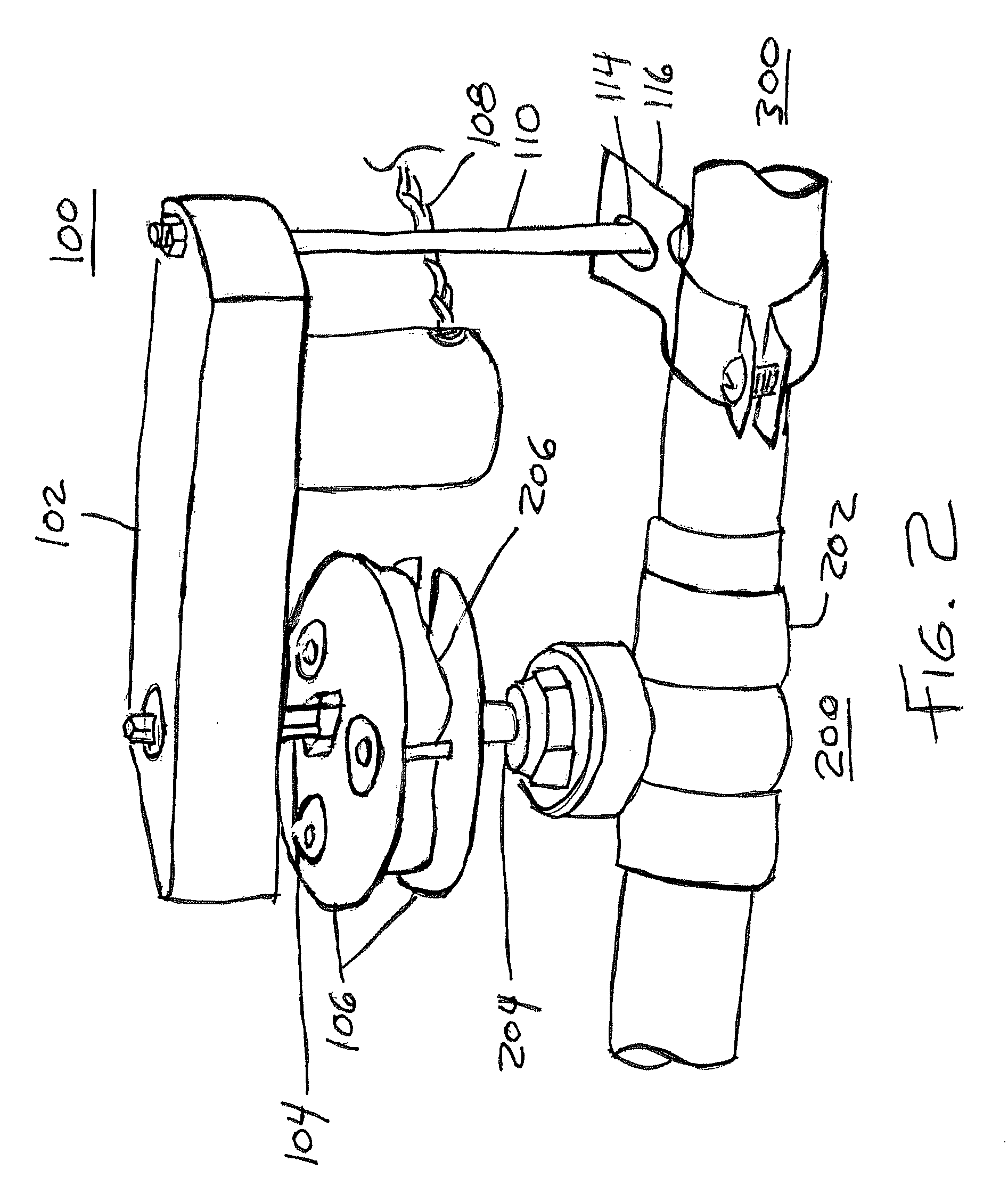
[0037]Referring to FIG. 1, the basic steps of one embodiment of the method of invention are illustrated. Step 1, “Attach drive shaft to handle”, refers to the configuring a valve handle 206 with a drive shaft 104, by the use of such suitable adaptors 106 and fasteners as may be required, so that when the valve handle 206 is properly mounted on the valve stem 204, the drive shaft 104 is axially aligned with the valve stem 204 but extends away from the valve 200, and is sufficiently well attached to support an actuator motor or motor assembly 102.

[0038]The terms actuator, motor, motor stator, motor assembly, and motor housing are used interchangeably throughout the specification and claims in so far as context admits. These terms are also meant to incorporate, in so far as context admits, any associated gear reduction means or m...


PUM

PropertyMeasurementUnit
time constantaaaaaaaaaa
rotational torqueaaaaaaaaaa
rotational forceaaaaaaaaaa

Abstract

A powered valve actuator assembly converts a manually operated valve without removal of the valve handle for automated valve operation in response to detection of a preselected condition. The design incorporates a motor, motor control circuit, drive shaft, valve handle engaging member and anti-rotation member. The motor is supported by its drive shaft, which is mounted on the valve handle via an adaptor. The motor, when operated, applies rotational torque to the drive shaft, and is secured from counter rotation about the drive shaft by the anti-rotation member, which extends between the motor and a fixed reference point with respect to the valve body such as the conduit or an extension thereof. The control circuit may incorporate a monitoring sub-circuit and power regulator, which operates at reduced power levels depending on the sensed state of the sensor or sensors.

Description

RELATED APPLICATIONS[0001]This application is a continuation-in-part of U.S. application Ser. No. 13 / 334,670, filed Dec. 22, 2011, which is a continuation-in-part of U.S. application Ser. No. 11 / 846,559, filed on Aug. 29, 2007, which claims the benefit of U.S. Provisional Application No. 60 / 823,798, filed Aug. 29, 2006. U.S. application Ser. No. 13 / 334,670 also claims the benefit of U.S. Provisional Application No. 61 / 425,933, filed Dec. 22, 2010. This application also claims the benefit of U.S. Provisional Application No. 61 / 672,825, filed Jul. 18, 2012. All applications are herein incorporated by reference in their entirety for all purposes.FIELD OF THE INVENTION[0002]The invention is related to the field of valve actuators and other rotary control devices, and more particularly to an electronically controlled, motorized valve actuator for adapting manually operated valves and rotary control devices to automated operation.BACKGROUND OF THE INVENTION[0003]Replacing a manually contr...

Claims


Application Information

Patent Timeline
Patent Type & Authority Patents(United States)
IPC IPC(8): F16K31/05F16K31/04
CPCF16K31/05F16K31/04F16K31/055Y10T29/49412
Inventor STAFFIERE, DONALDDRINKWATER, DON LSTAFFIERE, DAVIDST. JAMES, DANAPRAGER, JAY M
Owner TAEUS CORP
Why Eureka
Try Eureka