Stackable cube power distribution center

a technology of power distribution center and cube, which is applied in the direction of electrical equipment, substation/switching arrangement details, substation/switching arrangement casing, etc., can solve the problems of injury to persons attempting to lift the power distribution center, and the known power distribution center, particularly those which convert high voltage, such as 240 or 480 v voltage to 102 v voltage, are typically quite heavy

Inactive Publication Date: 2013-12-03
JNT TECHN SERVICES
View PDF10 Cites 9 Cited by
  • Summary
  • Abstract
  • Description
  • Claims
  • Application Information

AI Technical Summary

Problems solved by technology

However, known power distribution centers, particularly those which convert high voltage, such as 240 or 480 V voltage to 102 V voltage are typically quite heavy due to the large transformer and all of the associated wiring, switches, meters, and inlet and outlet connectors.
Oftentimes it is necessary to move the power distribution centers over obstacles which require the power distribution centers to be lifted rather than simply rolled, and the tight tolerance locations may prevent machinery or other equipment to be used for the lifting, and would require manual lifting efforts which exceeds available human lifting capabilities or could cause injuries to persons attempting to lift the power distribution centers in such situations.

Method used


Image

  • Stackable cube power distribution center
  • Stackable cube power distribution center
  • Stackable cube power distribution center

Examples


Embodiment Construction

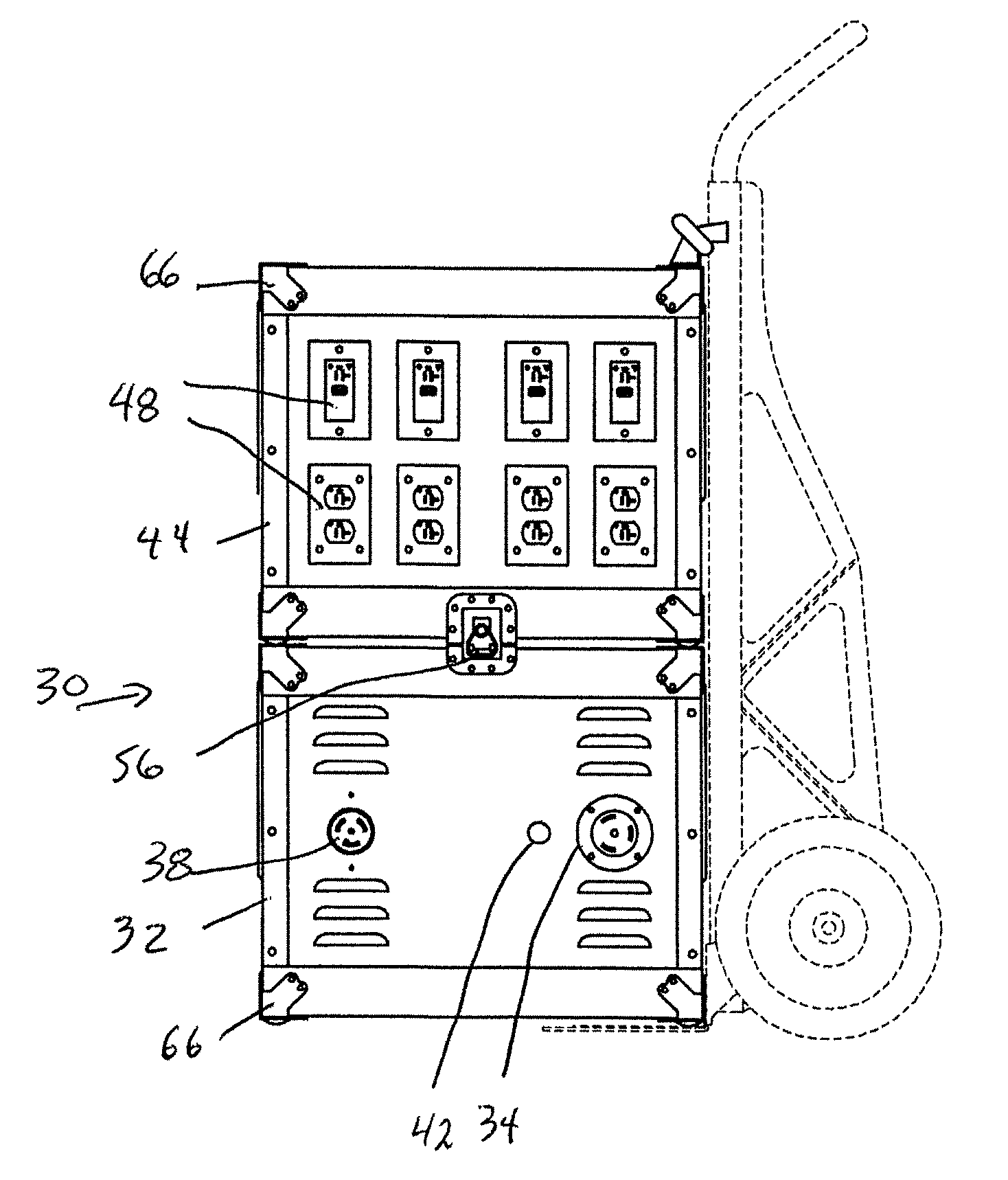
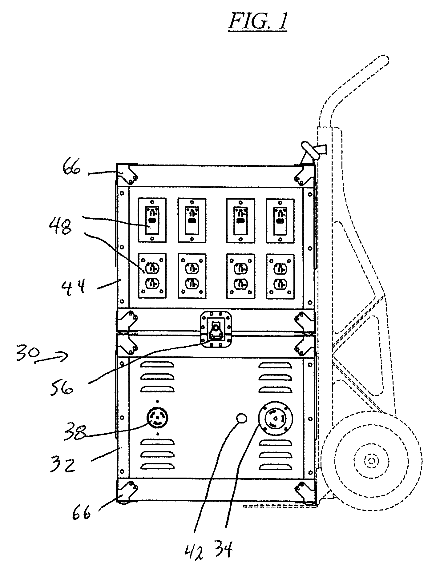
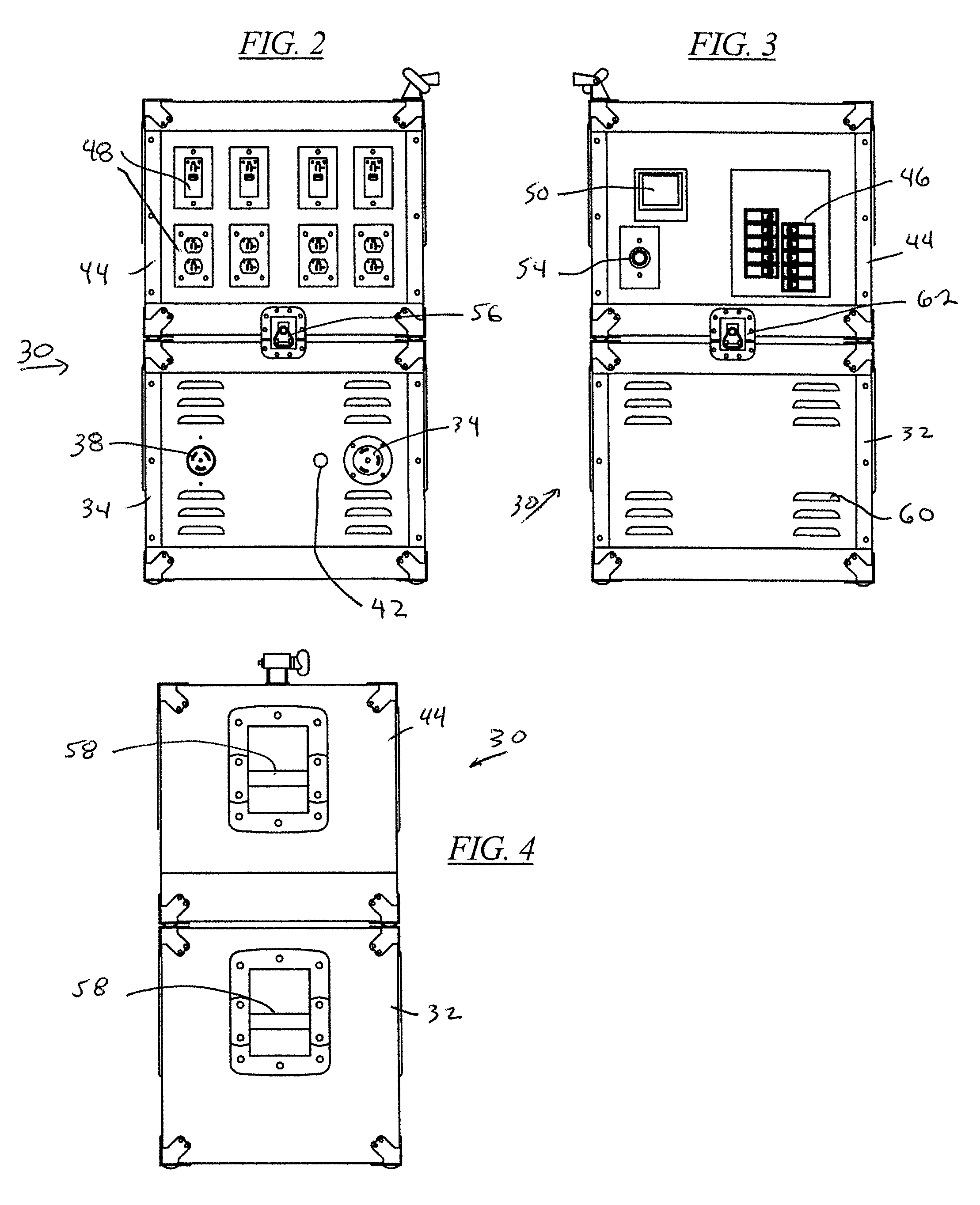
[0037]FIGS. 1-4, 7-12, 16-17 and 22-27 show a two piece stackable cube electrical power transformer 30 in the stacked condition. The bottom cube 32 includes a receptacle 34 for inputting 3 phase 480 V electrical current to a transformer 36 (FIG. 29) in the cube. The bottom cube 32 also includes a 480 V outlet receptacle 38. A disconnect switch 40 is also provided to deenergize the 480 V outlet receptacle 38 and a lamp 42 displays when power is supplied to the cubes.

[0038]The top cube 44 includes circuit breakers 46 (FIG. 30) for a number of individual circuits with outlet receptacles 48 providing either 120 V or 240 V current. The top cube 44 also includes a power meter 50, such as a DIRIS A20 power meter. A receptacle 52 for an Ethernet connection is provided that is connected to a web relay device to control a number of circuits within the cube. A 240 V outlet receptacle 54 is shown below the power meter.

[0039]A latch 56 is provided to secure the top cube 44 to the bottom cube 32....


PUM


Abstract

A power transformer and electrical current distribution device has a 480 V power inlet receptacle, at least one 120 V or 240 V power outlet receptacle, a transformer for transforming 480 V current to at least one of 120 V and 240 V current, and a first housing and a second housing each containing at least some of the 480 V inlet receptacle, the outlet receptacle and the transformer. A first part of an electrical connector is provided at the first housing, and a second part of an electrical connector at the second housing to mate with the first part of the electrical connector. The first housing part and the second housing part are electrically connected and disconnected at the electrical connector to permit transport of the power transformer and electrical current distribution device in at least two pieces.

Description

[0001]This application claims priority to and benefit of U.S. Provisional Application Ser. No. 61 / 390,679 filed Oct. 7, 2010, which is incorporated herein in its entirety.BACKGROUND OF THE INVENTION[0002]Portable power distribution centers are known which are movable on wheels or by means of two wheeled dollies. However, known power distribution centers, particularly those which convert high voltage, such as 240 or 480 V voltage to 102 V voltage are typically quite heavy due to the large transformer and all of the associated wiring, switches, meters, and inlet and outlet connectors. Oftentimes it is necessary to move the power distribution centers over obstacles which require the power distribution centers to be lifted rather than simply rolled, and the tight tolerance locations may prevent machinery or other equipment to be used for the lifting, and would require manual lifting efforts which exceeds available human lifting capabilities or could cause injuries to persons attempting ...

Claims


Application Information

Patent Timeline
Patent Type & Authority Patents(United States)
IPC IPC(8): H02B1/26
CPCH02B1/52
Inventor JORGENSEN, GLENN F.KELLY, MICHAEL W.
Owner JNT TECHN SERVICES
Why Eureka
Try Eureka