Spinner home sequence

a microfluidic device and spinner technology, applied in the direction of gas/liquid distribution and storage, volume/mass flow by differential pressure, liquid/fluent solid measurement, etc., can solve the problems of increasing complexity of the channel network, reducing the size of the channel, and not being able to transport liquid within a certain part of the system. , to achieve the effect of increasing the accuracy of the home position

Active Publication Date: 2013-12-03
GYROS
View PDF13 Cites 0 Cited by
  • Summary
  • Abstract
  • Description
  • Claims
  • Application Information

AI Technical Summary

Benefits of technology

[0023]It is an object of the present invention to present a new solution of said identification problem and to increase accuracy of a home position by means of a set of home position marks on a special microfluidic device type.
[0027]One advantage with the present invention is that the system will work faster and more properly, even though a lot of false marks are present on the device that would have normally disturbed the homing process.
[0028]Another advantage is that the yield will increase as less microfluidic devices have to be discarded.
[0029]Further one advantage is that the microfluidic system will be capable of detecting and warning if the microfluidic device is turned up-side down when inserted in the analysis system instrument.
[0030]Another advantage is that the present invention provides possibility to give different microfluidic devices a unique detectable identity.

Problems solved by technology

This means that there may or may not be liquid transport within a certain part of the system, for instance the microfluidic device / disc.
As work has progressed in each of these areas, the channel size has gradually decreased while the channel network has increased in complexity, significantly enhancing the overall capabilities of microfluidic systems.
A common problem is to identify a certain microfluidic device, e.g. within a series of identical microfluidic devices used within a series of experiments.
All extra equipment and program software increase the total cost for the system and also the system instrument.
The adding of an electronic label to the microfluidic device adds an extra cost to the total cost and increases the manufacturing complexity of the microfluidic device.
Suggested solutions of the identification problem are therefore not considered to be satisfactory from an economical point of view.
Even a very small deviation from the true home position may ruin a whole experiment run as the injection needles are not placed properly in the inlets of the micro-channels.
At occurrence of home position displacement, the aliquots and wash-liquids will be dispensed and wasted on the surface of microfluidic device.
Another problem with the use of only one home position mark is that the microfluidic device may be discarded if one of the edges of the home position mark is a defect edge.
The instrument system will not be able to identify the home mark and the microfluidic device will be rejected by the system.
Another problem with the known home position mark is that the home position detector is capable of detecting the home position mark even though the microfluidic device is placed up-side down.

Method used


Image

  • Spinner home sequence
  • Spinner home sequence
  • Spinner home sequence

Examples


Embodiment Construction

[0036]The present invention relates to microfluidic systems.

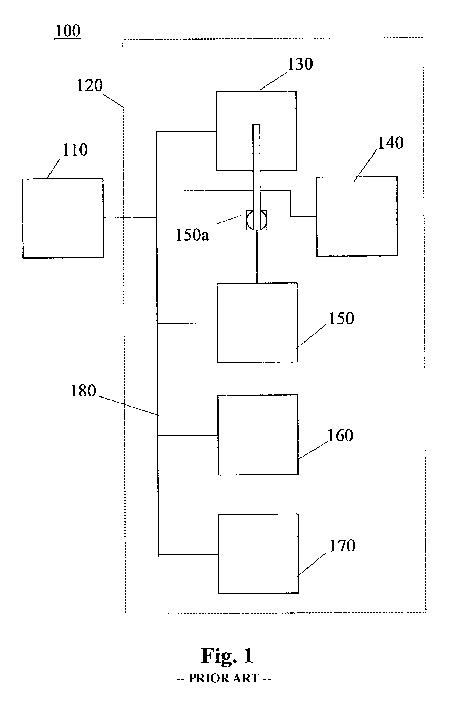
[0037]Different microfluidic systems are known. One type of systems comprises a controller unit and a microfluidic instrument. Such a system is called a Stand Alone System. Each system has its own data and operates completely stand alone. The interaction with the system may be performed at an associated Personal Computer (PC).

[0038]Another system can be considered as a group of instruments plus a common persistent storage location, e.g. database. Many instruments can operate on the same set of data (Method Data, Microfluidic Device Data, etc). All interaction with the system needs to be performed at an instrument connected computer, a controller. This second system is often called a Distributed Database Solution.

[0039]In a third solution, the distributed solution, the system is considered as a group of instruments, a common storage persistent storage location (database), and a number of clients. With this solution the same ...


PUM


Abstract

The present invention relates to a method for determining the identity of a microfluidic device and a home position by means of a set of home position marks on the microfluidic device, which is of the type used in a microfluidic system. Said method comprises following phases: a microfluidic device scanning phase, wherein a microfluidic device is scanned for mark identifiers; a microfluidic device identifying phase, wherein at least one a characteristic feature of the set of home marks is / are determined and used for identifying the identity of the microfluidic device; a home position determining phase, wherein the home position is determined by the use of at least a subset of the home position marks identified during said previous phases. The present invention relates to a set of home marks, a microfluidic device carrying such a set of home marks, a microfluidic system, a computer program product and a computer program on a computer usable medium.

Description

TECHNICAL FIELD[0001]The present invention relates to an identifying method of microfluidic devices used in microfluidic systems.[0002]More specifically, the present invention relates to sets of home position marks, a microfluidic device carrying such a set of home position marks, a method for determining the identity of a microfluidic device and determining the home position by means of a set of home position marks on a microfluidic device of a type used in a microfluidic system. The present invention also relates to a microfluidic system, a computer program product and a computer program on a computer usable medium.BACKGROUND OF THE INVENTION[0003]The term “microfluidic” refers to a system or device having one or a network of chambers and / or channels, which have micro scale dimensions, e.g., having at least one cross sectional dimension in the range from about 0.1 μm to about 500 μm. The term “microfluidic” in the context of device, system, disc etc refers to the fact that liquid ...

Claims


Application Information

Patent Timeline
Patent Type & Authority Patents(United States)
IPC IPC(8): F17D3/00G01B11/14
CPCB01L3/5027G01N35/00732B01L2200/025B01L2300/021B01L2300/0806G01N35/1011G01N2035/1034Y10T137/86389
Inventor OHLSTROM, AGNETABERGSTROM, MARTENSODERMAN, TOBIASBIELIK, ROBERT
Owner GYROS
Why Eureka
Try Eureka