Multiple-disk clutch with resilient element

a multi-disk, resilient element technology, applied in the direction of fluid-actuated clutches, clutches, non-mechanical actuated clutches, etc., can solve the problems of uneven pressing distribution, jerking of the vehicle or shaking during starting, etc., to improve the application of force and improve the pressing distribution

Active Publication Date: 2013-12-10
ZF FRIEDRICHSHAFEN AG
View PDF22 Cites 2 Cited by
  • Summary
  • Abstract
  • Description
  • Claims
  • Application Information

AI Technical Summary

Benefits of technology

[0009]Based on the prior art cited above, an object of the invention is to provide a multiple-disk clutch which has an improved application of force and, therefore, a better pressing distribution.
[0011]In this regard, it is advantageous that when the multiple-disk clutch is actuated the resilient element does not contact the adjacent disk proceeding from the first contacting edge area continuously along the center to the opposite edge area, but rather when the multiple-disk clutch is actuated the second edge area initially contacts the adjacent disk, and the resilient element does not contact the adjacent disk in the central edge area. Whereas in the prior art an application of force to the second edge area does not take place until the resilient element fully contacts the adjacent disk and, therefore, not until the end of the spring travel of the resilient element, an application of force to the second edge area takes place in the invention already much sooner and, therefore, while still in the springing range of the resilient element. Accordingly, the mean force application radius on the disk adjacent to the resilient element is not displaced continuously toward the radial center of the disk stack and only reaches the force application radius of the actuator substantially at the end of the spring travel of the resilient element. According to one embodiment of the invention, the mean force application radius is reached when the resilient element contacts the second edge area of the adjacent disk and then remains substantially constant over the rest of the spring travel.
[0012]In a particularly advantageous construction of the resilient element, the curve of the force application radius in the springing range of the resilient element has a step, while the force curve in the springing range is substantially linear. In this connection, it is advantageous that an advantageous control of the multiple-disk clutch is made possible by the linear force curve. Further, there is a smooth transition of the force curve from the springing range to the non-springing range when the resilient element contacts in a virtually flat manner.
[0017]In another preferred embodiment of the invention, the axial step corresponds to between 10% and 90%, preferably between 10% and 50%, of the thickness of the first area. In this connection, it is advantageous that the step can be stamped in the outer disk, which is preferably made of plate steel, and that the first area is axially offset from the second area by no more than the axial thickness in this area. Further, manufacturing tolerances are easier to keep under control in a step than in a plate spring. The second area of the resilient element preferably lies in a plane which is parallel to the first area and which is offset by the axial step. However, it may also be advantageous when, in addition to the step, the second area has an angle of preferably between 1° and 10°, most preferably between 1° and 5°, relative to the first area so that the second area slopes away from the adjacent disk and the second edge area is accordingly at a greater distance from the adjacent disk than only the height of the axial step. The combination of the step and the taper of the resilient element is advantageous in that the elasticity of the element can be adjusted and optimized during production by the step and the taper.
[0020]The axial oscillating capacity of the disk stack is advantageously reduced. Axial oscillations which would be transmitted from the actuator to the disk stack are reduced by the resilient element arranged between the actuator and the disk stack. In this way, the torque fluctuations due to variations in the thickness of the disks and the torque fluctuations due to axial oscillations or variations in the pressing force of the actuator are filtered out. The mass of the disk stack is supported at the opposite fixed axial stop and is accordingly decoupled from the oscillatable system.
[0022]In a particularly preferred construction of the actuator, the actuator acts on the central radius area of the resilient element by a spherical contact surface. In this connection, it is advantageous when the actuator acts on the area of the resilient element which does not yet contact the adjacent disk, and which therefore still acts in a springing manner, when the first edge area and second edge area make contact.

Problems solved by technology

Accordingly, variations in the thickness of individual disks can cause torque fluctuations in the torque transmitted by the clutch which can be transferred to the entire succeeding drivetrain and can lead to jerking of the vehicle or to shaking during starting.
However, the known solutions have the disadvantage that the springing elements only make contact in an edge area of the adjacent disk and, therefore, an uneven pressing distribution is introduced into the disk stack.

Method used


Image

  • Multiple-disk clutch with resilient element
  • Multiple-disk clutch with resilient element
  • Multiple-disk clutch with resilient element

Examples


Embodiment Construction

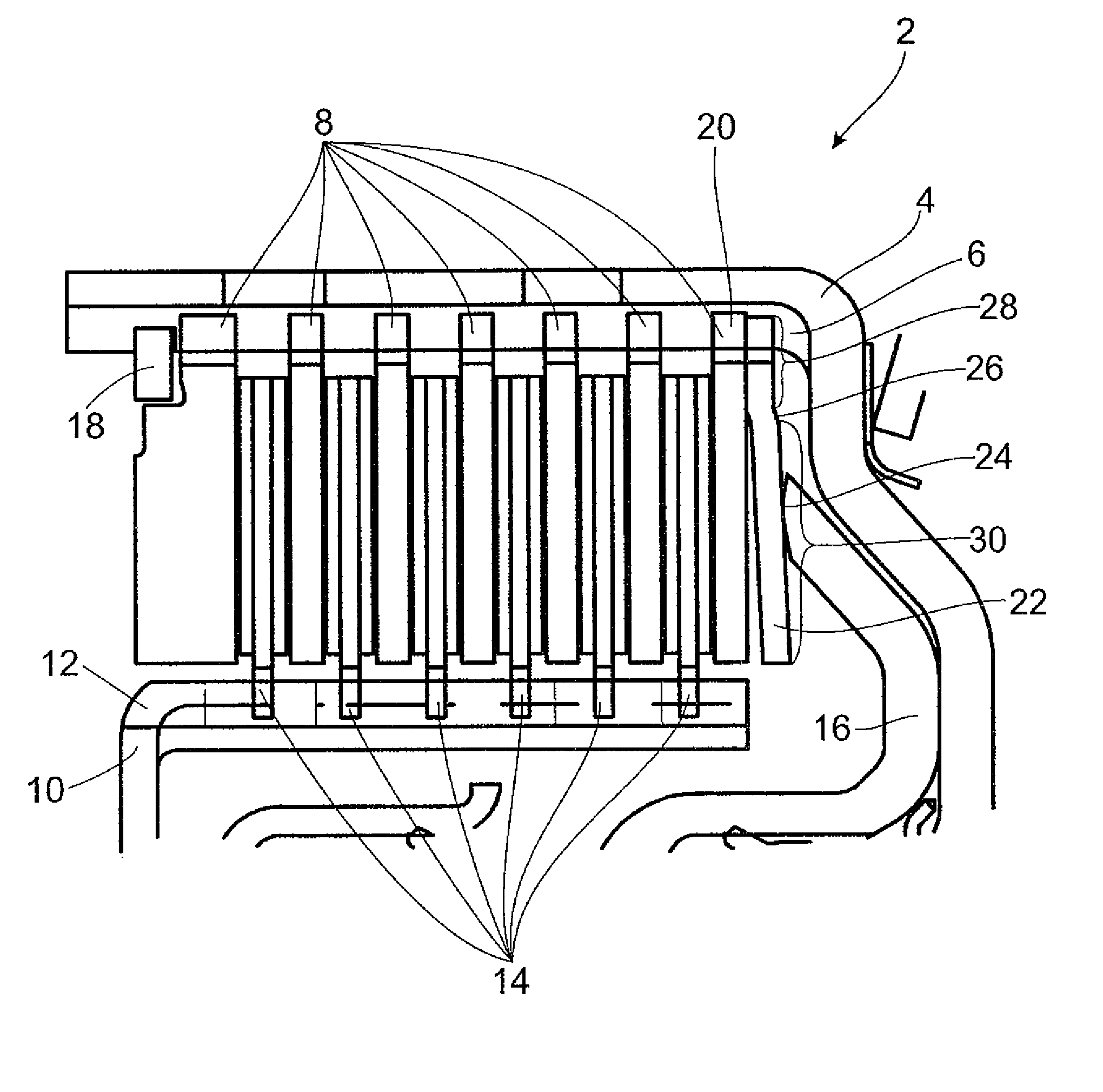
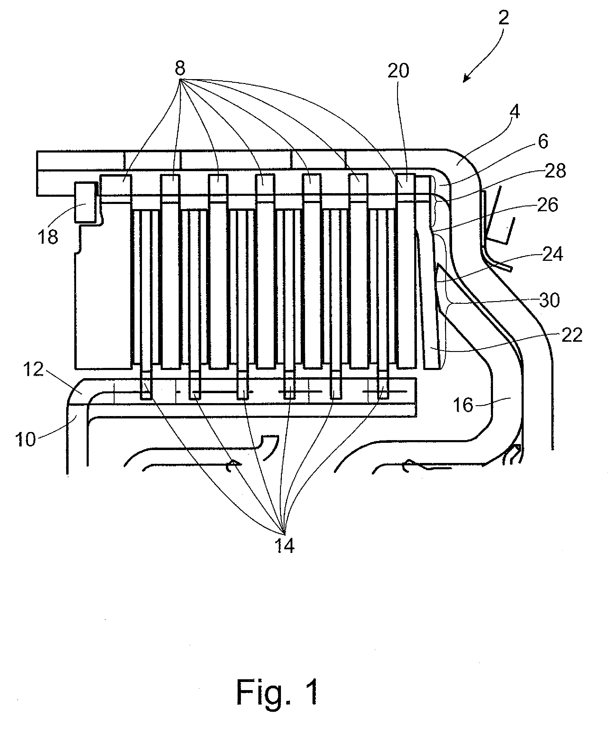
[0037]FIG. 1 shows a multiple-disk clutch 2 with an outer disk carrier 4 which has, at the inner circumferential surface, a spline profile 6 in which the outer disks 8 are arranged so as to be fixed with respect to rotation relative to it but so as to be displaceable axially. The inner disk carrier 10 has, at the outer circumferential surface, a spline profile 12 in which the inner disks 14 are arranged so as to be fixed with respect to rotation relative to it but so as to be displaceable axially. The inner disks 14 are constructed in this instance as faced disks and the outer disks 8 are constructed as steel disks. However, the reverse could also be possible. The actuator 16 is constructed as an axially displaceable piston. The disk stack is supported axially by an axial securing device in the form of a snap ring 18, which is held in a groove in the outer disk carrier 4. The end disk supported at the snap ring 18 is thicker than the other outer disks 8 to prevent bending. A resilie...


PUM


Abstract

Multiple-disk clutch with outer disks supported by an outer disk carrier that is rotatable around an axis of rotation and with inner disks supported by an inner disk carrier that is rotatable around the axis of rotation. The outer disks and the inner disks form an annular disk stack with an inner radius and an outer radius. An axially movable actuator actuates the disk stack. The actuator engages in a central radius area of the disk stack with reference to the axis of rotation when actuating. The disk stack includes a resilient element.

Description

BACKGROUND OF THE INVENTION[0001]1. Field of the Invention[0002]The invention is directed to a multiple-disk clutch in a drivetrain of a motor vehicle.[0003]2. Description of the Related Art[0004]Multiple-disk clutches of this kind are known. The multiple-disk clutches usually have an outer disk carrier with a spline profile at which outer disks are arranged so as to be fixed with respect to rotation relative to it and axially displaceable and an inner disk carrier with a spline profile at which inner disks are arranged fixed with respect to rotation relative to it and axially displaceable. The outer disks and inner disks are arranged in an alternating manner to form a disk stack. To transmit torque, the disk stack is pressed together by an actuator so that the disks are brought into frictional engagement. The disks can be constructed as steel plates and as faced disks. When actuated, one side of a disk, which has a facing, is always brought into frictional engagement with an adjace...

Claims


Application Information

Patent Timeline
Patent Type & Authority Patents(United States)
IPC IPC(8): F16D25/0638
CPCF16D13/52F16D25/0638F16D21/06F16D25/10F16D2021/0661
Inventor GROSSPIETSCH, WOLFGANGEBERT, ANGELIKAPITTNER, DANIEL
Owner ZF FRIEDRICHSHAFEN AG
Why Eureka
Try Eureka