Feed mixing device

A mixing device and feed technology, which is applied to feed, mixers with rotating stirring devices, mixers, etc., can solve the problems of poor mixing and separation effects, achieve good mixing effects, and improve the torque of the device

Inactive Publication Date: 2021-03-19
吕丹阳
View PDF0 Cites 1 Cited by
  • Summary
  • Abstract
  • Description
  • Claims
  • Application Information

AI Technical Summary

Problems solved by technology

[0004] Aiming at the deficiencies of the prior art, the present invention provides a feed mixing device, which solves the problem that the effect of the device mixing and separating the liquid feed that has been mixed with solid and liquid is relatively poor

Method used


Image

  • Feed mixing device
  • Feed mixing device
  • Feed mixing device

Examples


Embodiment example 1

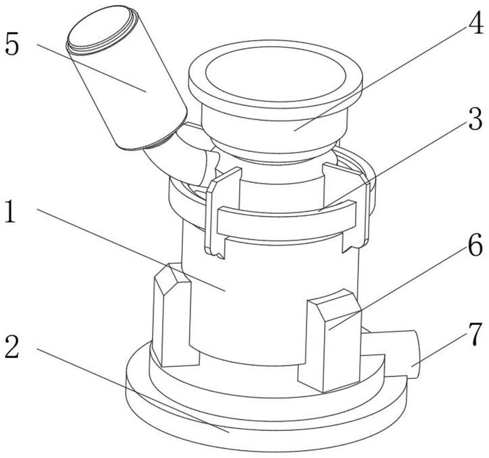
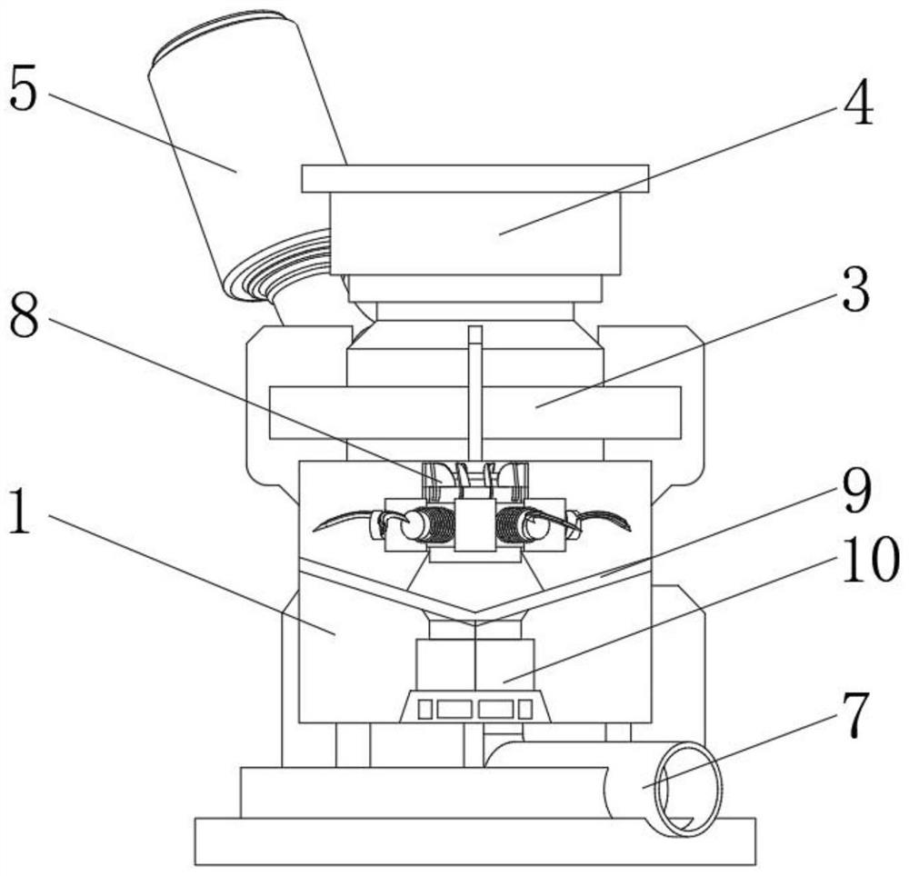
[0032] see Figure 1-2 , the present invention provides a technical solution: a feed mixing device, including a mixing tank 1, the bottom of the mixing tank 1 is fixedly connected with a base 2 by connecting a fixed foot frame 6, and the top of the mixing tank 1 is fixed by connecting a top seat 3 The top feed hopper 4 is connected, the top side of the mixing tank 1 is provided with a solvent liquid tank 5, and the outer discharge pipe 7 is arranged between the bottom of the mixing tank 1 and the base 2, and the outer discharge pipe 7 extends to the outside of the base 2. The top of the row pipe 7 communicates with the bottom of the mixing tank 1, the inner bottom of the mixing tank 1 is provided with a driving mechanism 10, the centrifugal filter disc 9 is installed above the driving mechanism 10, and the upper part of the mixing tank 1 is provided with a power motor. The output end is equipped with a mixing impeller 8, the mixing impeller 8 is located above the centrifugal f...

Embodiment example 2

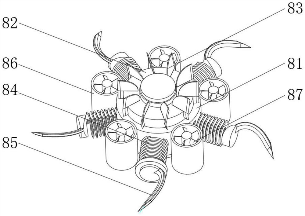
[0034] see Figure 1-4, on the basis of the implementation case 1, the present invention provides a technical solution: the mixing impeller 8 includes an inner disc body 81 and an outer rotating cylinder 86, the outer rotating drum 86 is evenly installed outside the inner disc body 81, and the inner disc body 81 passes through the upper disc The body 82 is equipped with an upper rotary vane 83, and the inner bottom of the outer rotary cylinder 86 is provided with a small motor. The purpose of the small composite impeller 87 is to uniformly mix the internal feed, and the small composite impeller 87 is mainly used for mixing liquid fertilizers. Multiple internal spirals can mix the internal fertilizer more evenly. By setting different rotation directions, it can also make The inner multiple spiral flow is reversed, and the mixing effect is better.

[0035] A space is provided between the outer rotating cylinders 86, and a spiral spring knife 84 is installed on the outer side of...

Embodiment example 3

[0038] see Figure 1-7 , on the basis of implementation case 1 and implementation case 2, the present invention provides a kind of technical scheme: centrifugal filter disc 9 comprises filter disc body 91, and the inner side of filter disc body 91 is provided with processing inner tank 92 and direct separation filter tank 94, processing A rotary treatment terminal 93 is arranged on the inner side of the inner tank 92, a filter separation arc knife 97 is arranged in the middle of the inner side of the inner tank 92, and a centrifugal separation filter hole 96 is arranged on the inner side of the inner tank 92 to directly separate the inside of the filter tank 94. A straight filter hole 95 is provided, and the center of the filter disc body 91 is provided with an outer row center hole, and an electromagnetic switch valve is installed at the bottom of the outer row center hole.

[0039] The rotary processing terminal 93 includes a circular terminal body 931 and a central shaft 93...


PUM


Abstract

The invention discloses a feed mixing device. The device comprises a mixing tank, the bottom of the mixing tank is fixedly connected with a base through a connecting and fixing foot stand, the top ofthe mixing tank is fixedly connected with a top feeding hopper through a connecting top seat, a solvent liquid tank is arranged on the side of the top of the mixing tank, a discharging pipe is arranged between the bottom of the mixing tank and the base, the discharging pipe extends to the outer side of the base, the top end of the discharging pipe communicates with the bottom of the mixing tank, adriving mechanism is arranged on the bottom side of the interior of the mixing tank, and a centrifugal filter disc is installed above the driving mechanism. The invention relates to the technical field of feeds. According to the feed mixing device, a mixing impeller and the centrifugal filter disc can be set to rotate in the same direction or opposite directions, during rotating in the same direction, the torque of the device can be increased, and the force applied by the device to internal feed can be increased; and during rotation in opposite directions, a feed in the device can move in opposite directions, and the internal feed can be mixed more uniformly.

Description

technical field [0001] The invention relates to the technical field of feed, in particular to a feed mixing device. Background technique [0002] With the rapid development of my country's artificial breeding industry, the demand for artificial feed is also increasing, which puts forward higher requirements for the production of feed. Therefore, it is also necessary to continuously improve equipment to meet the needs of the new era. The scale and quality of all walks of life are improving. Machinery gradually replaces manpower and improves efficiency. The scale of animal husbandry also continues to develop and improve. Feed, as the main material, needs to be mixed and stirred. Traditional feed processing technology It is to crush the raw materials first and then mix them. However, this traditional process requires different raw materials to be crushed separately, and its crushing efficiency is low. To enhance work efficiency, it is necessary to purchase multiple crushing dev...

Claims


Application Information

Patent Timeline
Patent Type & Authority Applications(China)
IPC IPC(8): B01F13/10A23N17/00A23N17/02B01F7/16B01F15/00
CPCA23N17/007A23N17/02B01F27/171B01F27/1921B01F27/808B01F33/8305B01F33/86B01F33/83612B01F35/187B01F2101/18
Inventor 吕丹阳
Owner 吕丹阳
Why Eureka
Try Eureka