Piston type drain clearing apparatus

a technology of drain clearing and pipe pipe, which is applied in the direction of water installations, lavatory sanitory, construction, etc., can solve the problems of causing pressure pulses to be transmitted to the obstruction, unable to deliver sufficient force to the obstruction, and many problems, etc., to achieve the effect of minimizing splashing, increasing the force applied, and maximizing the sealing

Inactive Publication Date: 2006-06-20
WALSH PATRICK JAMES
View PDF2 Cites 2 Cited by
  • Summary
  • Abstract
  • Description
  • Claims
  • Application Information

AI Technical Summary

Benefits of technology

[0007]It is another object of the invention to provide a piston type drain cleaning apparatus that utilizes a mechanical advantage to increase the force applied to a clog in a pipe.
[0008]It is a further object of the invention to provide a seal between the drain cleaning apparatus and the clogged drain pipe that minimizes splashing and maximizes the sealing effect.
[0009]It is yet another object of the invention to provide an inexpensive, easy to use, and lightweight clean-out tool that can be comfortably used by persons who lack sufficient physical strength to successfully use the common and well-known toilet plunger.

Problems solved by technology

The user depresses on the handle, deforming the rubber cup and thus creating pressure pulses that are transmitted to the obstruction.
Several problems are often encountered when attempting to use the common toilet plunger.
In particular, sufficient force is often not delivered to the obstruction because of the inability to maintain an adequate seal.
Even if an adequate seal of the plunger cup over the outlet is achieved, substantial physical effort may be required to successfully clear the obstruction.
In addition, splashing of the toilet bowl contents can happen if the seal is not maintained while plunging.
But the snake device can require even more physical effort on the part of the user, is difficult to employ, and is messy.
The disadvantages of this method are that the chemical agent is very caustic and must be handled with great care as well as the fact that the agent must be repeatedly purchased as it is consumed.

Method used


Image

  • Piston type drain clearing apparatus
  • Piston type drain clearing apparatus
  • Piston type drain clearing apparatus

Examples


Embodiment Construction

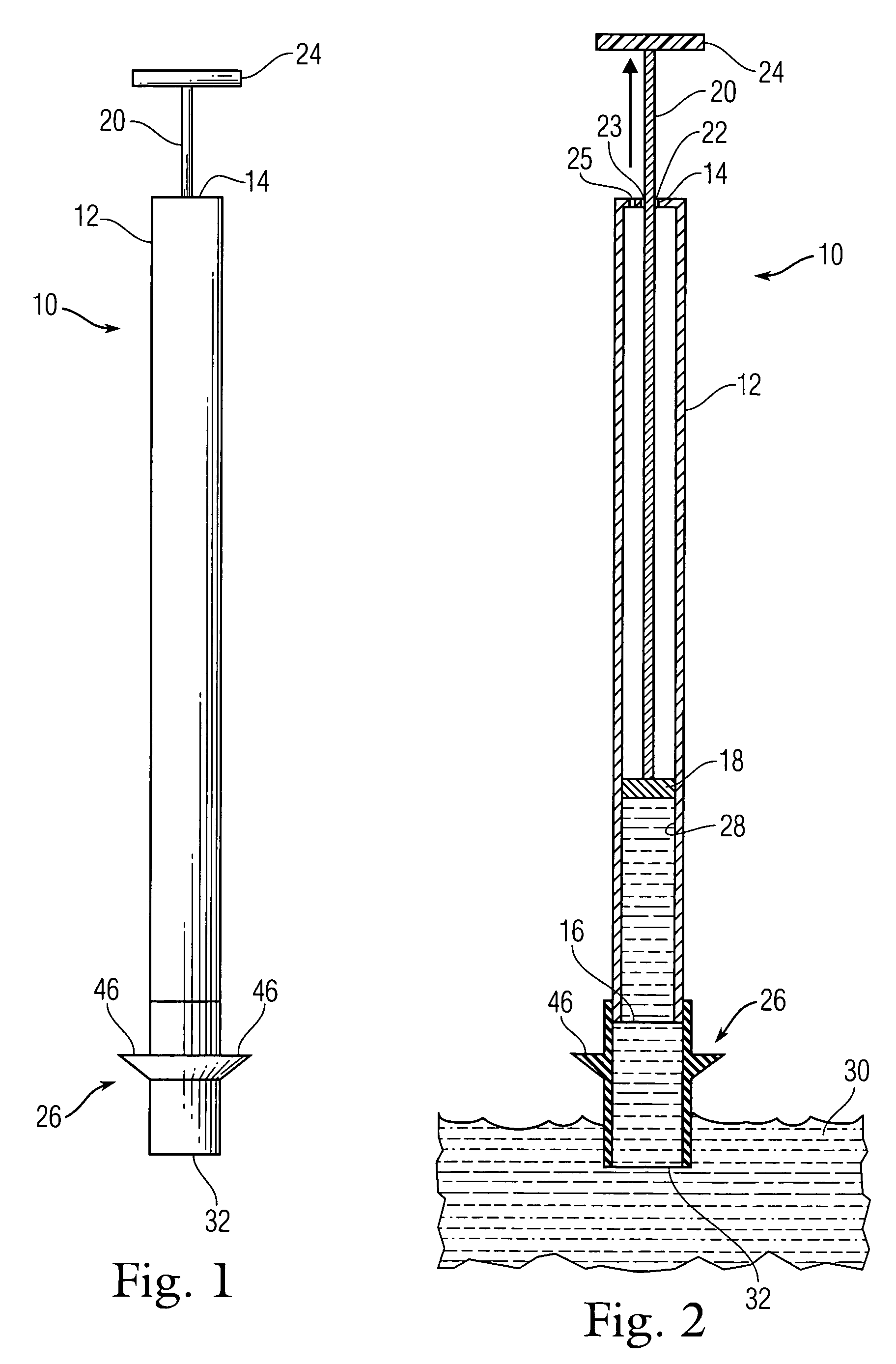
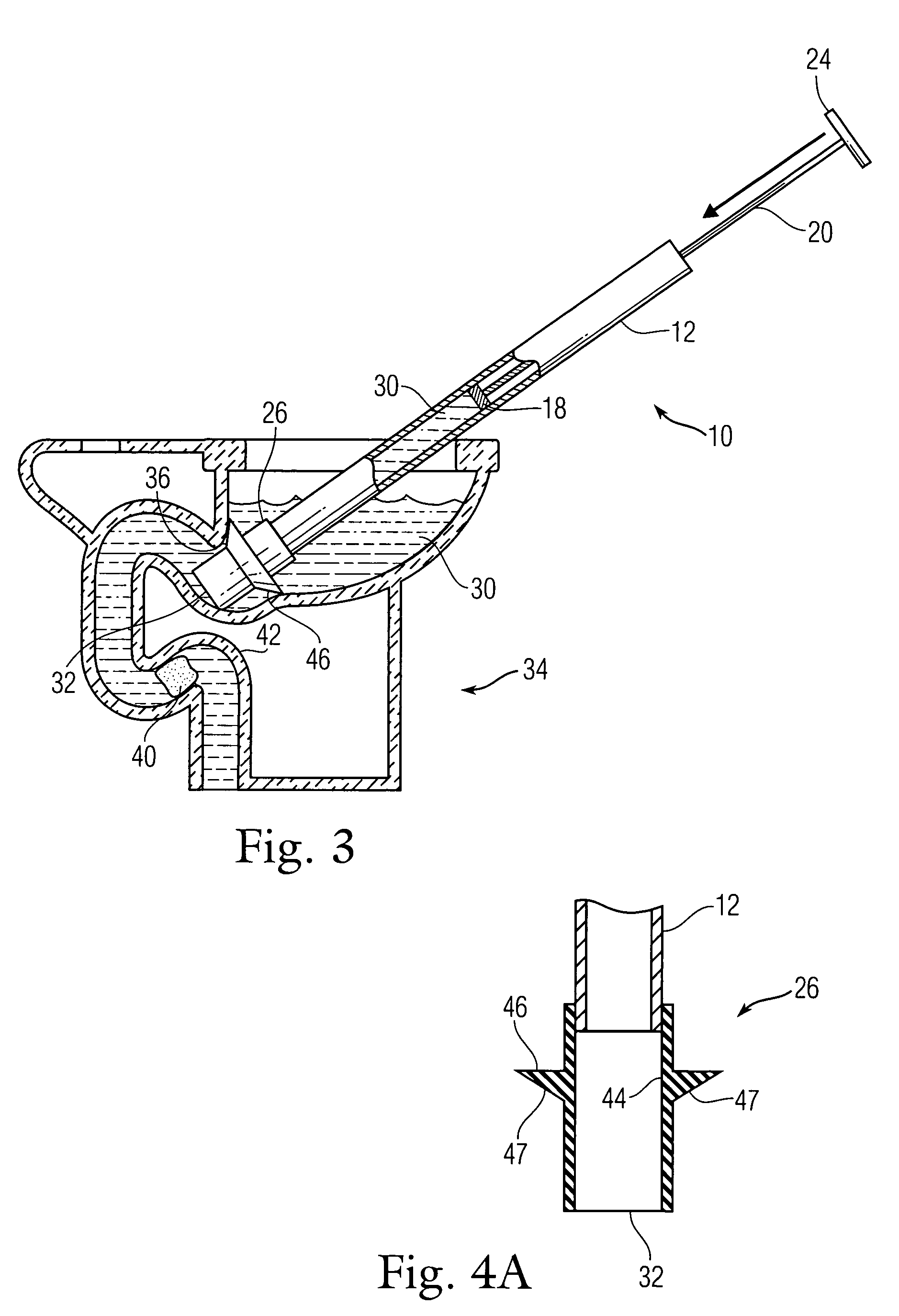
[0022]FIG. 1 is a side view of one embodiment of a drain clearing apparatus 10 according to the invention. FIG. 2 is a partial cross-sectional view of the embodiment of FIG. 1 showing water being drawn up into its hollow tube and end section. Apparatus 10 includes a hollow, rigid cylindrical body 12. Body 12 has a closed end 14 and an open end 16. A piston 18 is disposed in the body 12 for reciprocation therein. A rod 20 is attached to the piston 18 and extends through an opening 22 in the closed end 14 of the body 12. A handle 24 is located on an upper portion of the rod 20. A seal 26 is attached to the open end 16 of the body 12. Seal 26 is slipped over the lower end of body 12 and attached thereto by, for example, using adhesive to bond seal 26 to the lower end of body 12.

[0023]The handle 24 and the rod 20 may be made of, for example, plastic, metal, or another rigid material, preferably waterproof. The body 12 may be made of, for example, plastic, metal, or another sturdy waterp...


PUM


Abstract

An apparatus for clearing a clog in a pipe that includes a hollow, rigid cylindrical body, the body having a closed end and an open end; a piston disposed in the body for reciprocation therein; a rod attached to the piston and extending through an opening in the closed end of the body; a handle located on an upper portion of the rod; and a seal attached to the open end of the body. In one embodiment, the seal includes at least one flexible flange formed on an external surface thereof.

Description

CROSS-REFERENCE TO RELATED APPLICATIONS[0001]This application is a divisional application of U.S. patent application Ser. No. 10 / 465,739 filed on Jun. 19, 2003, entitled “Piston Type Drain Clearing Apparatus.” The aforementioned patent application is hereby expressly incorporated by reference. The subject matter of the instant application is also related to the subject matter of prior copending application Ser. No. 10 / 615,006 filed on Jul. 8, 2003, entitled “Drain Clearing Apparatus and Seals” and having the same inventor as the instant application.BACKGROUND OF THE INVENTION[0002]The invention relates in general to drain clearing devices and in particular to piston type drain clearing devices.[0003]The common toilet plunger is well known for its use in clearing toilet drain outlets and comprises a wooden handle that terminates in a resilient, flexible rubber cup. The user depresses on the handle, deforming the rubber cup and thus creating pressure pulses that are transmitted to the...

Claims


Application Information

Patent Timeline
Patent Type & Authority Patents(United States)
IPC IPC(8): E03D9/00E03C1/308
CPCE03D9/00E03C1/308
Inventor WALSH, PATRICK JAMES
Owner WALSH PATRICK JAMES
Why Eureka
Try Eureka