Connector assembly including first connector and second connector configured to be mounted on a circuit board and easily mated

a technology of connectors and assemblies, applied in the direction of coupling device details, coupling contact members, coupling device connections, etc., can solve the problem that the structure of the disclosed connector assemblies is not suitable for a low-profile design

Active Publication Date: 2013-12-10
JAPAN AVIATION ELECTRONICS IND LTD
View PDF28 Cites 9 Cited by
  • Summary
  • Abstract
  • Description
  • Claims
  • Application Information

AI Technical Summary

Benefits of technology

[0005]It is therefore an object of the present invention to provide a connector assembly which has a new structure suitable for a low-profile design.

Problems solved by technology

However, the structures of the disclosed connector assemblies are not suitable for a low-profile design.

Method used


Image

  • Connector assembly including first connector and second connector configured to be mounted on a circuit board and easily mated
  • Connector assembly including first connector and second connector configured to be mounted on a circuit board and easily mated
  • Connector assembly including first connector and second connector configured to be mounted on a circuit board and easily mated

Examples


first embodiment

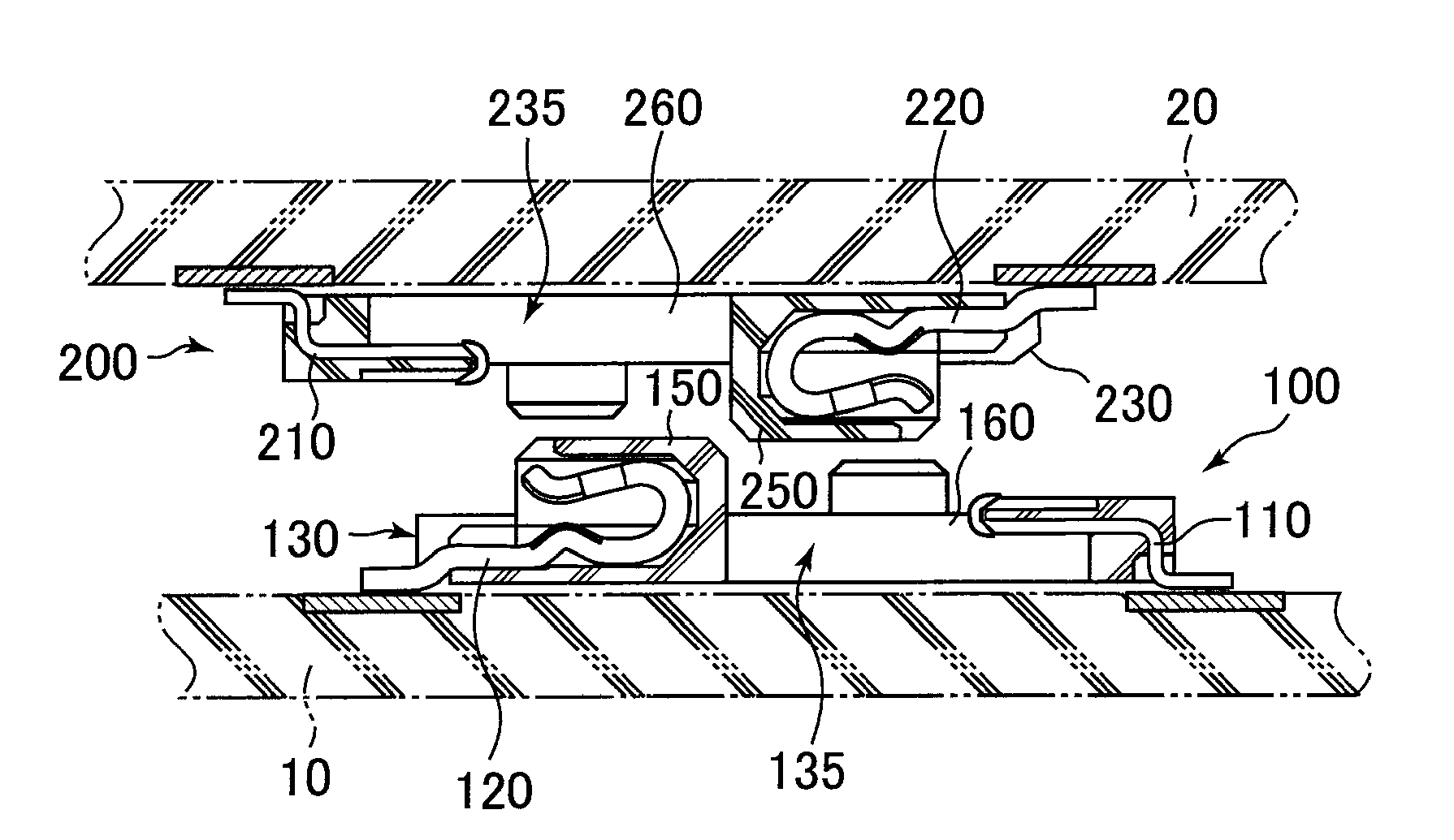
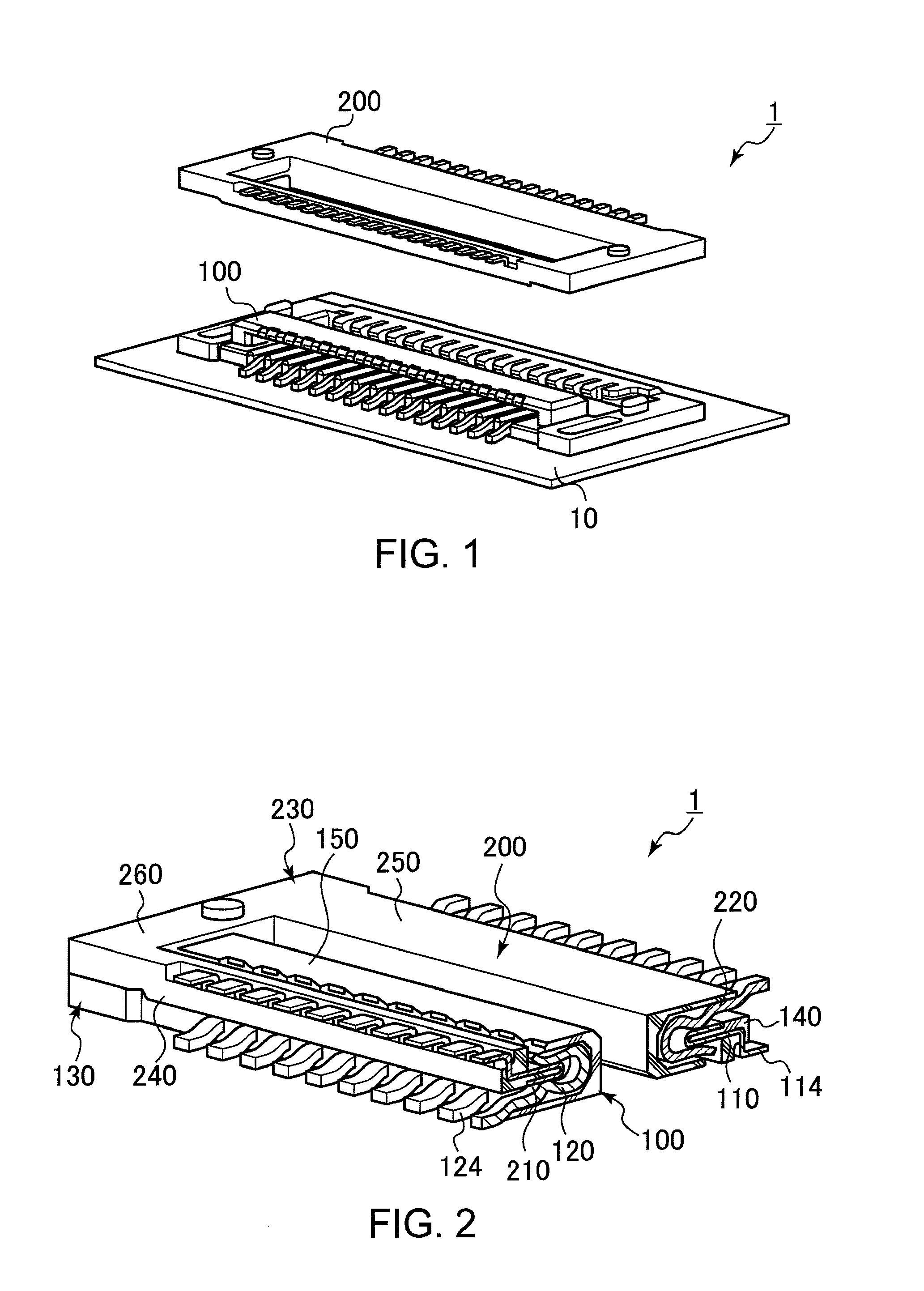
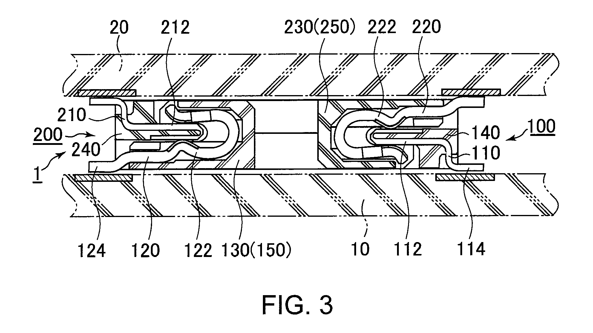
[0036]With reference to FIGS. 1 to 8, a connector assembly 1 of the first embodiment of the present invention comprises a first connector 100 and a second connector 200. The first connector 100 and the second connector 200 are installed on and fixed to a first circuit board 10 and a second circuit board 20, respectively. As understood from FIGS. 1 to 3, 7 and 8, a structure of the first connector 100 is same as another structure of the second connector 200.

[0037]With reference to FIGS. 4 to 6, the first connector 100 comprises a plurality of first male terminals 110, a plurality of first female terminals 120 and a first holding member 130. The first holding member 130 holds the first male terminals 110 and the first female terminals 120. The first male terminals 110 and the first female terminals 120 are made of metal.

[0038]With reference to FIGS. 5 and 6, each of the first male terminals 110 comprises a first male contact 112 and a first male SMT terminal 114. The first male contac...

second embodiment

[0062]With reference to FIG. 9, a first connector 100a of the second embodiment of the present invention comprises a first male terminal 110a which has a crank-like shape when seen along the third horizontal direction. The first male holding portion 140a of the present embodiment has a rectangular-like cross-section in a plane perpendicular to the third horizontal direction and extends in the third horizontal direction. The first male holding portion 140a holds the first male terminals 110a so that the first male contacts 112a projects from the first male holding portion 140a and is oriented in the first horizontal direction.

[0063]The first male terminals 110a are held by the first male holding portion 140a by insert-molding process. However, the first male terminals 110a may be press-fitted into the first male holding portion 140a.

third embodiment

[0064]With reference to FIGS. 10 and 11, a first connector 100b of the third embodiment of the present invention comprises a first holding member 130b which has no projection portion 162 or groove portion 164 shown in FIG. 4. Similarly to the first holding member 130 of the first embodiment (see FIG. 4), the first holding member 130b comprises a first male holding portion 140b, a first female holding portion 150b and the first connection portion 160b. The first male holding portion 140b holds a plurality of first male terminals 110b. The first female holding portion 150b holds a plurality of first female terminals 120b. The first connection portion 160b connects the first male holding portion 140b and the first female holding portion 150b in the first horizontal direction. The first connection portion 160b comprises two connection bridges. The first connector 100b of the present embodiment further comprises two hold-downs 170 made of metal. As shown in FIG. 11, the hold-downs 170 ar...


PUM


Abstract

A first connector has a first holding member holding first male and female terminals. Each first male terminal has a horizontally extending first male contact. Each first female terminal has a first female contact. A second connector has a second holding member holding second male and female terminals. Each second male terminal has a horizontally extending second male contact receivable in the first female contact. Each second female terminal has a second female contact which receives the first male contact. The first and second connectors are positioned at a predetermined position in a vertical direction whereas the first male contact is apart from the second female contact while the second male contact is apart from the first female contact. A guiding mechanism guides the first connector to a position where the first and second male contacts are respectively connected to the second and first female contacts.

Description

CROSS REFERENCE TO RELATED APPLICATIONS[0001]Applicant claims priority under 35 U.S.C. §119 of Japanese Patent Application No. JP 2010-079568 filed Mar. 30, 2010 and JP 2010-157589 filed Jul. 12, 2010.BACKGROUND OF THE INVENTION[0002]The present invention relates to a connector assembly which comprises two connectors to be connected with each other.[0003]JP-A 2007-109522 or JP-A 2000-260509 discloses a connector assembly for interconnecting a pair of circuit boards, the contents of JP-A 2007-109522 and JP-A 2000-260509 being incorporated herein by reference in their entirety.[0004]However, the structures of the disclosed connector assemblies are not suitable for a low-profile design.SUMMARY OF THE INVENTION[0005]It is therefore an object of the present invention to provide a connector assembly which has a new structure suitable for a low-profile design.[0006]One aspect of the present invention provides a connector assembly which comprises a first connector, a second connector, a pos...

Claims


Application Information

Patent Timeline
Patent Type & Authority Patents(United States)
IPC IPC(8): H01R13/64
CPCH01R12/716H01R12/73H01R13/02H01R24/84H01R12/71H01R13/115
Inventor TAKAHASHI, TAKUYA
Owner JAPAN AVIATION ELECTRONICS IND LTD
Why Eureka
Try Eureka