Image sensor with wide dynamic range

a technology of image sensor and dynamic range, which is applied in the field of cmos image sensor, can solve the problems of processing images that contain motion artifacts, the scene to be photographed is often too dark, and the lighting conditions are not ideal, and achieves the effect of wide dynamic rang

Active Publication Date: 2013-12-10
SAMSUNG ELECTRONICS CO LTD
View PDF31 Cites 29 Cited by
  • Summary
  • Abstract
  • Description
  • Claims
  • Application Information

AI Technical Summary

Benefits of technology

[0009]In an alternate embodiment, the signal read out and reset timing controller adds additional row read out delay time at the end of each frame, in order to thereby increase the second time interval beyond a normal time required to read one frame without physically increasing the size of the image sensor (i.e. the controller processes “phantom” rows).
[0010]In another embodiment, an image sensor comprises a plurality of pixel rows, each row comprising a plurality of pixels, a plurality of first signal lines equal to a number of pixels rows in the sensor, wherein each first signal line is connected to a first sub-set of pixels in one row of pixels; a plurality of second signal lines equal to the number of pixel rows in the sensor, wherein each second signal line is connected to a second sub-set of pixels in one row of pixels; and a timing controller connected to the plurality of first and second signal lines to control the read out of pixels on a row-by-row basis, wherein the first sub-set of pixels in a respective row is read out at a first time period, and the second sub-set of pixels is read out at a second time period following the first time period and before a next row is read out, and wherein the timing controller resets the pixels in the first sub-set of pixels in a respective row at a first integration start time interval and resets the second sub-set of pixels in a respective row at a second integration start time interval. The second sub-set of pixels is reset before the first sub-set of pixels such that the second sub-set of pixels has a longer integration time than the first sub-set of pixels. Alternately, the second sub-set of pixels can be reset at the same time as the first sub-set of pixels, while having started its integration epoch at a different time than the first sub-set of pixels thereby having either a longer or shorter integration time.
[0014]The present invention includes a method for increasing the dynamic range of an image sensor, the image sensor comprising a plurality of pixel rows, each pixel row comprising a plurality of pixels, the method comprising reading out a first sub-set of pixels in a first row during a first time period; reading out a second sub-set of pixels in the first row during a second time period, but before reading pixels from a next row; resetting the pixels in the first sub-set of pixels after a first integration start time interval X; and resetting the pixels in the second subset of pixels after a second integration start time interval Y. The method preferably comprises resetting the first sub-set of pixels initially after reading, and resetting the second sub-set of pixels initially after reading. In one embodiment, the first integration start time interval X is equal to a time period to read out X rows of the sensor and the second integration start time interval Y is equal to a time period to read out Y rows of the sensor. In one embodiment, X is greater than Y, such that the second sub-set of pixels has a longer signal integration time than the first sub-set of pixels. In another embodiment, Y is great than X, such that the first sub-set of pixels has a longer signal integration time than the second sub-set of pixels. In an alternate embodiment, either X or Y is equal to a time period greater than a time required to read out all rows in the image sensor, such that an integration time for pixels is greater than a normal frame period. The method preferably includes processing the pixel signals from the first and second sub-set of pixels from each row in the image sensor to form a single image.

Problems solved by technology

In digital photography, rarely are the lighting conditions ideal.
The scene to be photographed may be too dark, too light, too diverse, or too dynamic, such as when a cloud quickly blocks the sun.
However, a drawback to such an approach is that the processed images often contain motion artifacts caused by movement in the scene between the different exposures.
Another major drawback is that the different exposures are taken at different times and can thus wholly represent different images.
The problem with such a solution is that the dynamic range of the sensor is effectively fixed by the selected filters and filter pattern, regardless whether the selected filter pattern also includes a color structure, such as Bayer filter matrix, or is monochromatic with a structure having alternating optical transmittance.

Method used


Image

  • Image sensor with wide dynamic range
  • Image sensor with wide dynamic range
  • Image sensor with wide dynamic range

Examples


Embodiment Construction

[0031]The following description is provided to enable any person skilled in the art to make and use the invention and sets forth the best modes contemplated by the inventor for carrying out the invention. Various modifications, however, will remain readily apparent to those skilled in the art. Any and all such modifications, equivalents and alternatives are intended to fall within the spirit and scope of the present invention.

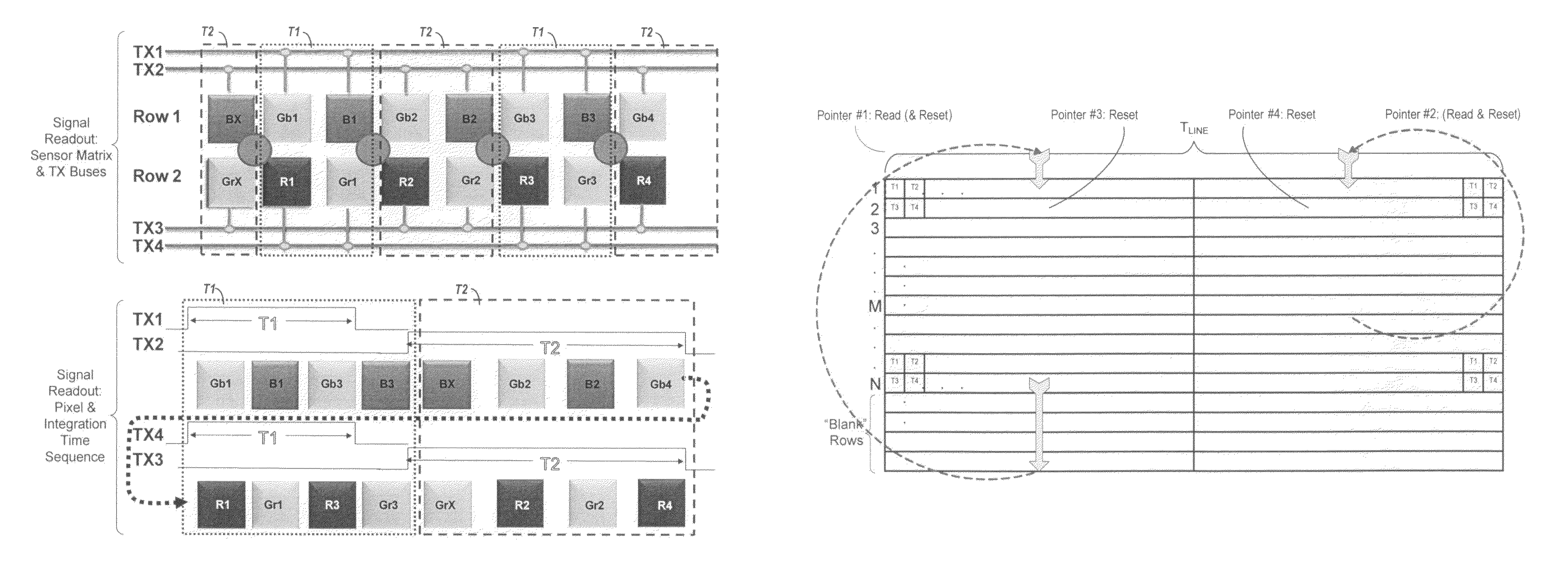
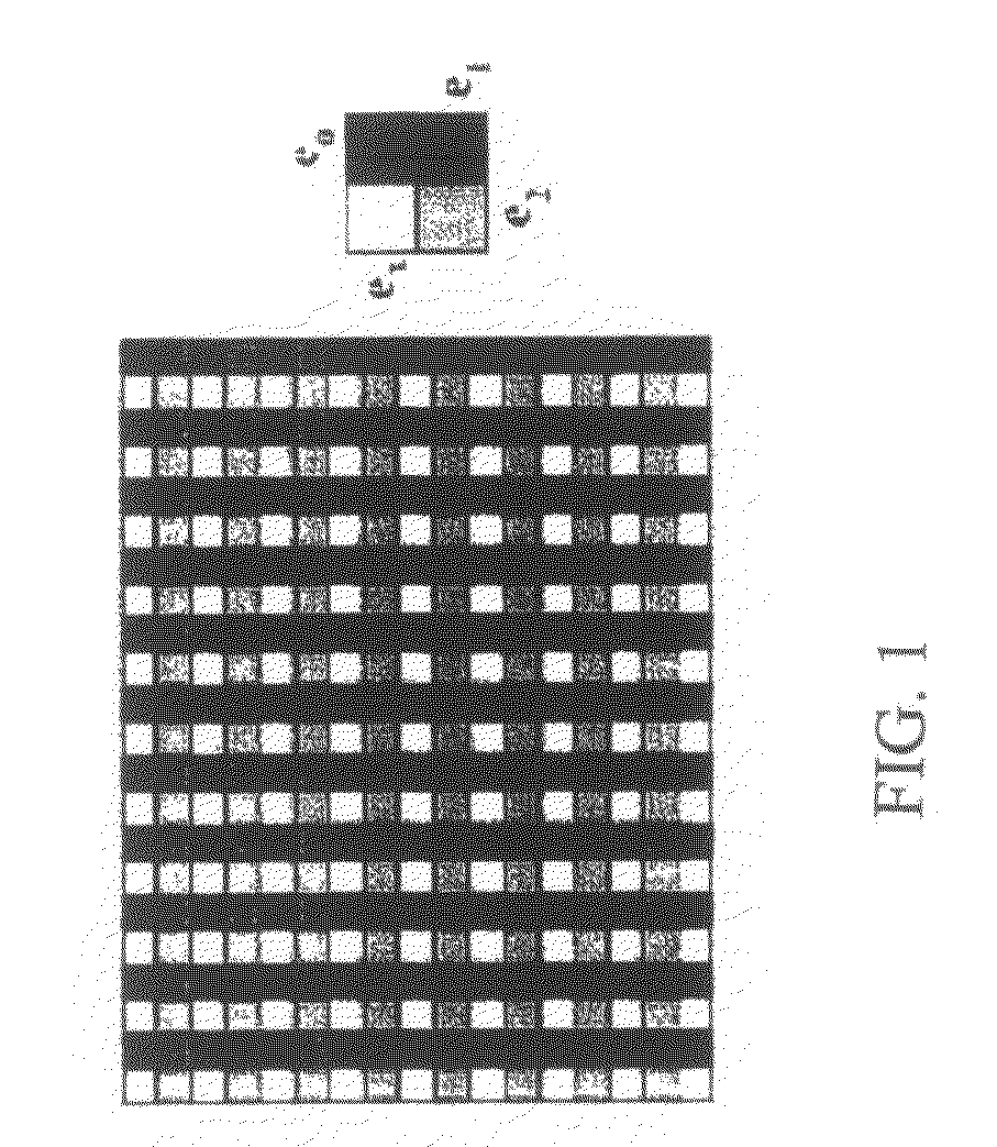
[0032]According to the present invention, a unique checkerboard pattern of filters is deposited on an image sensor, wherein different sub-blocks of pixels have different integration times. Since the integration times can be programmably varied, the dynamic range of the sensor can be continuously adjusted. Moreover, since the long and short exposure times are combined in a single contiguous frame of the full image sensor, there are only negligible motion artifacts, compared to prior art WDR images.

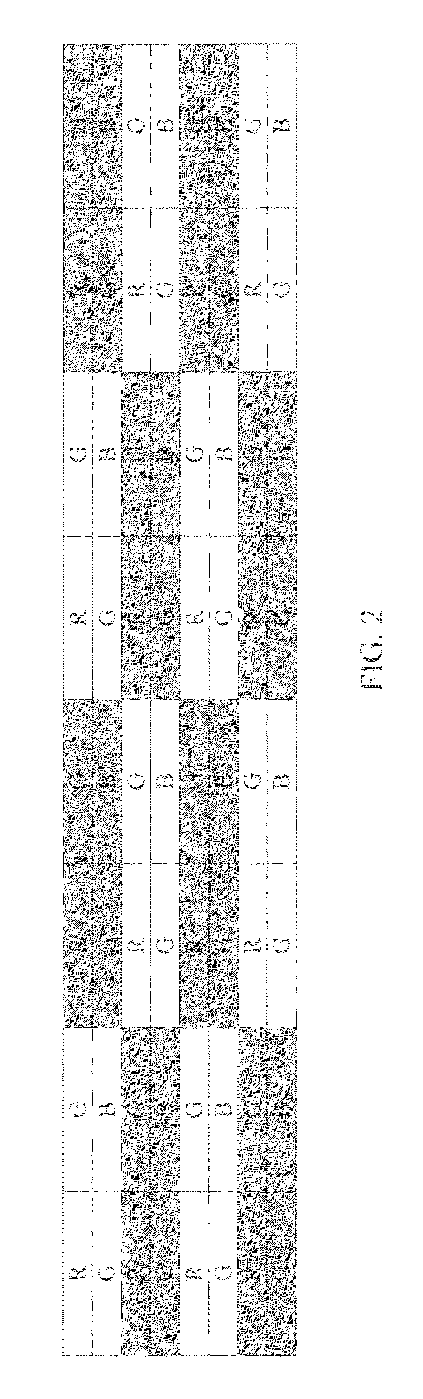
[0033]For example, as shown in FIG. 2, alternating sub-blocks of ...


PUM


Abstract

An image sensor, system and method that alternates sub-sets of pixels with long exposure times and pixels with short exposure times on the same sensor to provide a sensor having improved Wide Dynamic Range (WDR). The sub-sets of pixels are reset at different time intervals after being read, which causes the respective integration times to vary. By combining information contained in the both the short and long integration pixels, the dynamic range of the sensor is improved.

Description

BACKGROUND OF THE INVENTION[0001]1. Field of the Invention[0002]The present invention relates generally to CMOS image sensors, and more particularly to a sensor, system and method for utilizing pixels with long exposure times and pixels with short exposure times on the same sensor to provide a sensor with a wide dynamic range.[0003]2. Description of the Related Art[0004]In digital photography, rarely are the lighting conditions ideal. The scene to be photographed may be too dark, too light, too diverse, or too dynamic, such as when a cloud quickly blocks the sun. In order to adjust to different lighting conditions, an image sensor needs to have a wide dynamic range. That is, the sensor should be able to adjust to the current lighting conditions to maximize the details in the image, and thereby produce the best possible picture.[0005]Many scenes contain useful information in both shadow and bright areas which are traditionally very difficult to image at the same time. A recurring pri...

Claims


Application Information

Patent Timeline
Patent Type & Authority Patents(United States)
IPC IPC(8): H04N5/335H04N5/228H04N5/235
CPCH04N5/3454H04N5/3741H04N5/35554H04N25/443H04N25/583H04N25/766H04N25/134H04N25/531H04N25/533H04N25/445
Inventor ROSSI, GIUSEPPEMARCHESINI, ROBERTOMAO, QIANJIANGMANDELLI, EMANUELEPATEL, GAURANGKOLLI, NAVEENSTERN, JONATHAN
Owner SAMSUNG ELECTRONICS CO LTD
Why Eureka
Try Eureka