Roving machine for producing a roving

a roving machine and roving technology, applied in the field of roving machines, can solve the problems of increased protective twist, increased bending, and higher angular velocity, and achieve the effect of preventing clogging and facilitating the infeed of sliver

Active Publication Date: 2013-12-17
MASCHINENFABRIK RIETER AG
View PDF8 Cites 3 Cited by
  • Summary
  • Abstract
  • Description
  • Claims
  • Application Information

AI Technical Summary

Benefits of technology

[0009]It is advantageous if at least in the region of the inlet port of the spindle, the vortex chamber has an inner diameter with a value between 10 mm and 16 mm, preferably between 12 mm and 14 mm, further preferably a value of 12.5 mm. In this region, the inlet port of the spindle is surrounded by an adequate wall section, wherein the wall section and the inlet port are preferably arranged concentrically. This results in an annular flow channel between the spindle tip (=region around the inlet port) and the wall of the vortex chamber, in which flow channel, the vortex flow required for forming the protective twist is generated by the inflowing air. At a certain applied pressure which effects that the air flows into the vortex chamber, the rotational speed of the resulting air vortexes within the vortex chamber depends now in particular on the inner diameter of the vortex chamber. If this diameter is too wide, the rotational speed is too low to generate a stable protective twist. If the diameter is too small and thus the rotational speed too high, the protective twist has a strength which counteracts the subsequent drafting, for example within an air jet spinning process. In contrast, when adhering to the aforementioned limits and the diameter range according to the invention of the spindle's inlet port, an optimal air flow is obtained that facilitates the generation of the desired protective twist.
[0013]Likewise, it is advantageous if the fiber guiding channel, while maintaining the diameter according to the invention of the spindle's inlet port, has a length, the value of which lies between 4 mm and 12 mm, preferably between 6.0 mm and 9.5 mm. The mentioned length allows a secure guiding of the sliver into the region of the vortex chamber by units adequately arranged upstream, for example an apron drafting frame, without the risk of excessive friction between the sliver and the inner wall of the fiber guiding channel.
[0014]Furthermore, it is advantageous if the fiber guiding channel, on its side facing away from the infeed opening of the vortex chamber, has a sliver entry opening, the height of which has a value that lies between 2 mm and 10 mm, preferably between 4 mm and 5 mm. Hereby, the slivers can be guided into the fiber guiding channel without the occurrence of undesired false drafting. In fact, clogging is prevented so that the negative pressure generated by the air flow inside the vortex chamber can propagate counter to the sliver's direction of motion and toward the entry opening of the fiber guiding channel and can facilitate the infeed of the sliver into the vortex chamber.
[0015]Likewise, it is advantageous if the fiber guiding channel, on its side facing away from the vortex chamber's infeed opening, has a sliver entry opening, the width of which has a value that lies between 5 mm and 12 mm, preferably between 7 mm and 8 mm. Here, the width lies in the order of the diameter of the inlet port of the spindle. Thus, during its transport through the spinning station, the sliver is not subjected to significant width fluctuations that could negatively influence the quality of the produced roving.
[0017]As a result, a roving machine is proposed that allows to produce a roving from a sliver by means of adequate air flows within a vortex chamber. By selecting the individual parameters according to the invention in connection with a spindle inlet port that has a diameter described above, the delivery speed can be considerably increased with respect to conventional roving machines, e.g. in the form of a flyer. In addition, only by maintaining the diameter of the inlet port of the spindle between 4 mm and 12 mm, which diameter thus lies significantly above the maximum diameter of known air jet spinning machines, it is ensured that a roving is obtained that has the required strength and still can be drafted in a subsequent spinning process. A particularly advantageous ratio between strength and draftability is finally achieved if the above-mentioned diameter lies between 6 mm and 8 mm.

Problems solved by technology

A smaller diameter results in more bending and vice versa.
A smaller diameter would result in a higher angular velocity whereby the wrap fibers are extensively twisted resulting in an increased protective twist and a loss of draftability.
In contrast, an outer diameter greater than 14 mm would result in an angular velocity which is too low and thus in a poor protective twist.

Method used


Image

  • Roving machine for producing a roving
  • Roving machine for producing a roving
  • Roving machine for producing a roving

Examples


Embodiment Construction

[0023]Reference will now be made to embodiments of the invention, one or more examples of which are shown in the drawings. Each embodiment is provided by way of explanation of the invention, and not as a limitation of the invention. For example features illustrated or described as part of one embodiment can be combined with another embodiment to yield still another embodiment. It is intended that the present invention include these and other modifications and variations to the embodiments described herein.

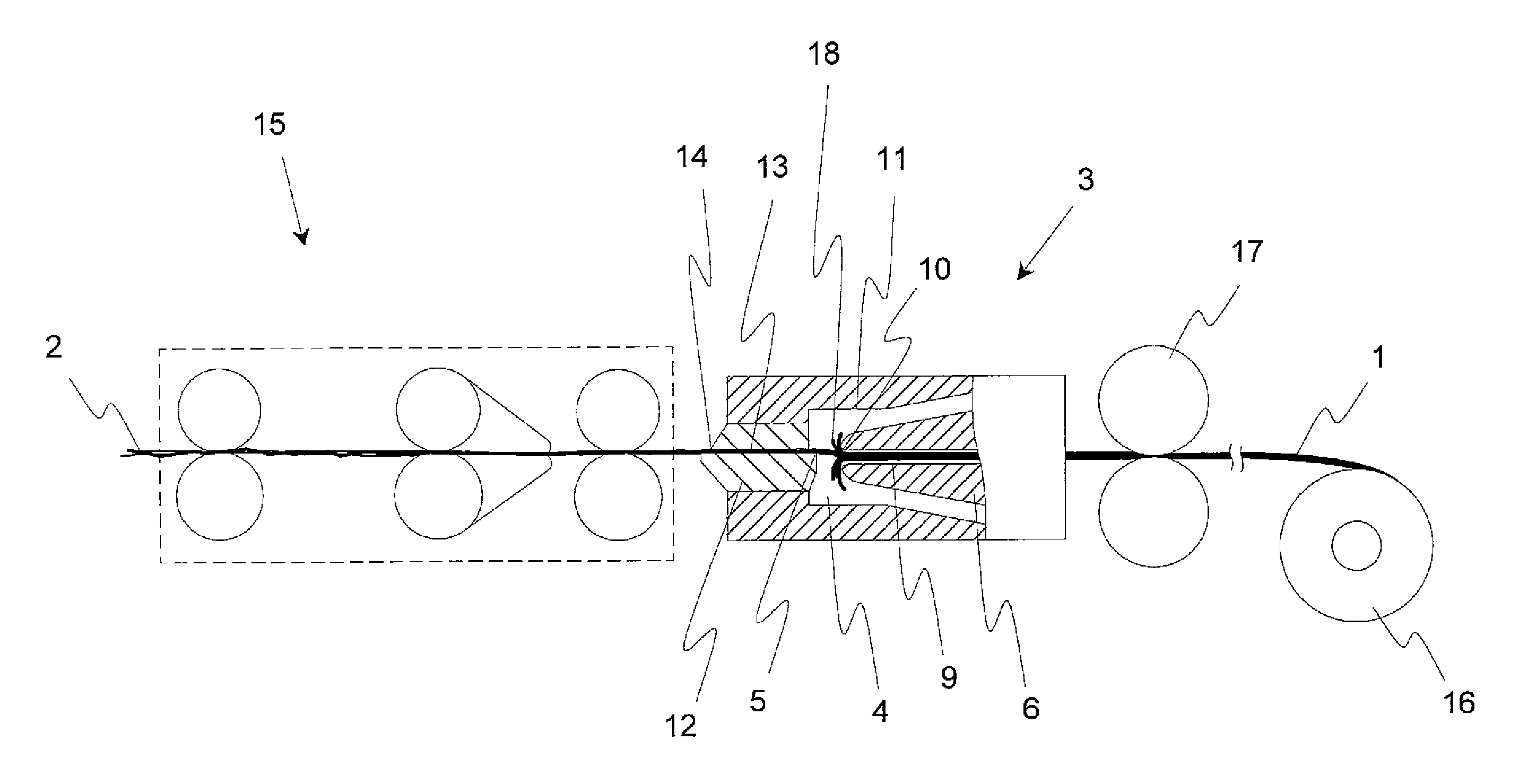
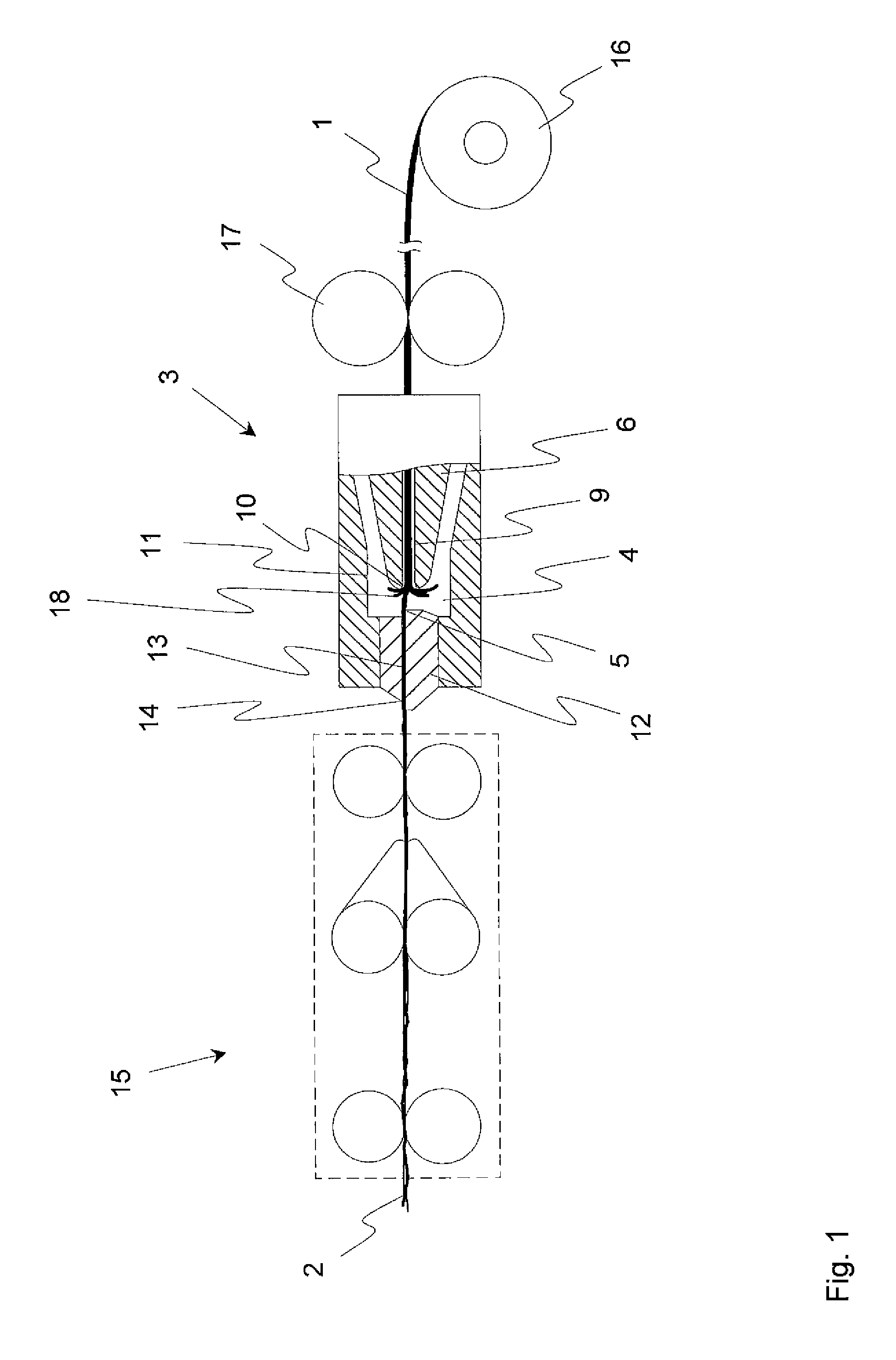
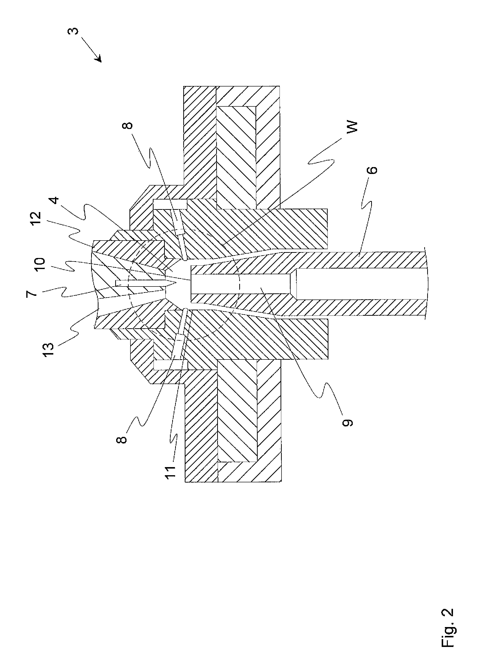
[0024]At the beginning of the description of the figures, it is explicitly to be noted that the illustrated spinning stations 3, as well as the elements potentially arranged upstream or downstream thereof, are not drawn to scale. Rather, the individual figures merely show schematic drawings which are intended to clarify the principal structure of the respective assemblies. In particular, the distances and diameters marked in each case in the FIGS. 3 and 4 show values in the drawing...


PUM

PropertyMeasurementUnit
diameteraaaaaaaaaa
diameteraaaaaaaaaa
outer diameteraaaaaaaaaa

Abstract

A roving machine for producing a roving from a sliver has at least one spinning station that has a vortex chamber with an infeed opening for the sliver and a roving forming element in the form of a spindle extending at least partially into the vortex chamber. The vortex chamber is associated with at least one air nozzle via which air is guided into the vortex chamber, and wherein the spindle has a draw-off channel via which the roving is drawn out of the vortex chamber. In the region of the vortex chamber, the draw-off channel has an inlet port for the roving to be drawn out of the vortex chamber, wherein the inlet port has an inner diameter that lies between 4 mm and 12 mm, preferably between 6 mm and 8 mm.

Description

FIELD OF THE INVENTION[0001]The present invention relates to a roving machine for producing a roving from a sliver, wherein the roving machine comprises at least one spinning station which has a vortex chamber with an infeed opening for the sliver and a roving forming element in the form of a spindle which extends at least partially into the vortex chamber. The vortex chamber is associated with at least one air nozzle through which air can be guided into the vortex chamber, and wherein the spindle has a draw-off channel via which the roving can be drawn out of the vortex chamber.BACKGROUND[0002]Roving machines for producing roving from (e.g. doubled) slivers, which are in most cases pretreated by means of drafting, have been known in the art for a long time. The roving in turn serves as feed for the subsequent spinning process in which the individual fibers of the roving are spun into a fiber yarn, for example by means of a ring spinning machine. During the production of the roving,...

Claims


Application Information

Patent Timeline
Patent Type & Authority Patents(United States)
IPC IPC(8): D01H7/00
CPCD01H1/115D01H4/02D01H7/92
Inventor BETZ, DOROTHEEKUPPERS, SIMON
Owner MASCHINENFABRIK RIETER AG
Why Eureka
Try Eureka