Single use sterilization container

a single-use, sterilization container technology, applied in the direction of caps, liquid handling, bandages, etc., can solve the problems of generating very small tears or snags, other sources of very small tears or breaches in the barrier may develop in the wrap, and increasing the cos

Active Publication Date: 2014-01-07
O&M HALYARD INC
View PDF87 Cites 16 Cited by
  • Summary
  • Abstract
  • Description
  • Claims
  • Application Information

AI Technical Summary

Benefits of technology

[0013]The permeable filter provides a path for a sterilant to enter the chamber from outside the container. The permeable filter also maintains aseptic conditions inside the chamber after sterilization by allowing gases such as air to enter or exit the chamber without allow passage of microorganisms. The permeable filter is desirably located in the central portion of the lid and is located in communication with one or more openings and / or passages between the outside of the container and the chamber. However, the permeable filter and the opening(s) and / or passage(s) in communication with the filter may be located in other portions of the lid or even the tray. The permeable filter may be a conventional filter material used for sterilization container applications. It should be inexpensive enough to be discarded or recycled with the tray and the lid after a single use. Exemplary filter materials include, for example, nonwoven filter materials such as polyolefin meltblown materials and nonwoven laminate materials such as laminates of spunbond materials and meltblown materials.
[0023]Generally speaking, the container may desirably be formed of, or include sections containing, a substantially transparent material adapted to withstand exposure to steam, ethylene oxide, or other forms of sterilization without degradation of the tray. This allows the contents of the container to be at least partially visible after sterilization of the container and prior to removal of the lid. Desirably, the container may be made of a recyclable material such as, for example, a thermoplastic polymeric material. Exemplary materials include, but are not limited to, polypropylene, polyethylene, polyesters and olefinic copolymers and the like. In another aspect of the invention, the material used to form the sterilization container may result in a sterilization container that is substantially rigid or may have portions of the container that are substantially rigid while other portions are less than substantially rigid or are more flexible.

Problems solved by technology

Although utilization of sterilization wrap and / or use of vented rigid reusable sterilization containers are generally effective, there are certain disadvantages associated with each of these items.
These sterilization trays have pointed edges or other features that may concentrate forces and generate very small tears or snags if the wrap contacts these features.
When wrapped trays are transported on carts or stacked prior to sterilization or after sterilization, other sources of very small tears or breaches in the barrier may develop in the wrap due to pressure or impact.
These tears may allow bacteria or other harmful substances to contaminate the items which results in added expense because the items to be sterilized will need to re-handled and re-sterilized at an additional cost.
An additional issue with the use of sterilization wraps is a lack of visibility.
Because sterilization wraps generally are not made of transparent material, the medical professional utilizing it cannot visually inspect the items contained therein for content or for assurance that the sterilization procedure has been completed.
This can lead to a medical professional opening the wrong sterilization tray during a procedure and / or lead to lack of confidence that the tray is truly sterilized.
As a result, trays and articles may require unnecessary re-handling and re-sterilization which wastes both economic and time resources.
Reusable sterilization containers require significant amounts of hospital economic and time resources because staffing levels often need to be increased in order to process and maintain these rigid containers for re-use.
Additionally, the longer the containers are in use, the less confidence clinicians have in the sterilization efficacy of the containers.

Method used


Image

  • Single use sterilization container
  • Single use sterilization container
  • Single use sterilization container

Examples


Embodiment Construction

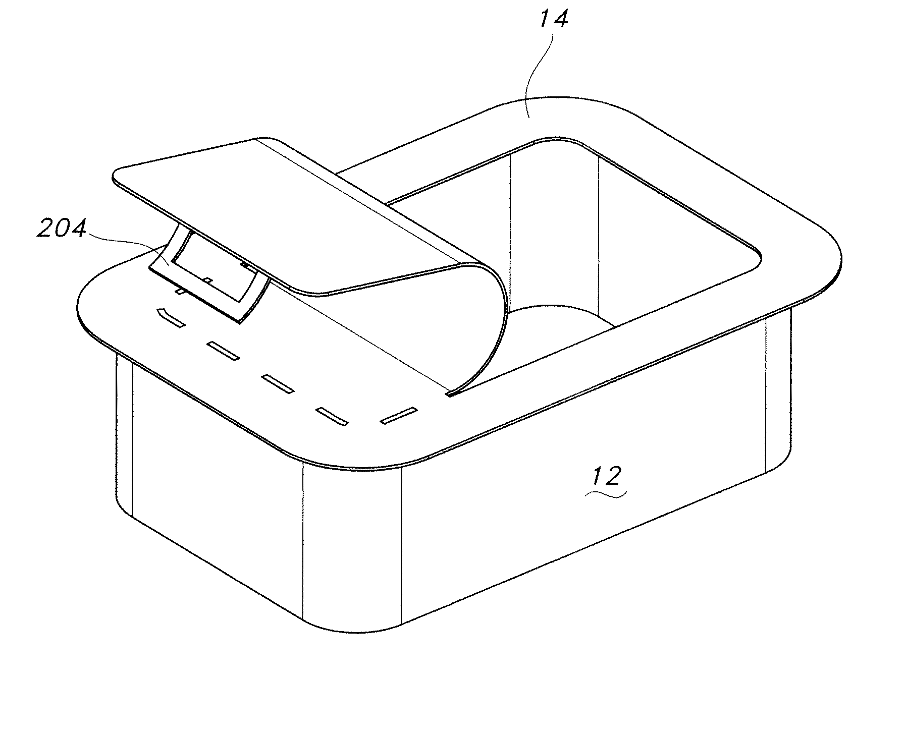
[0056]The present invention provides a non-reusable, locking container for sterilizing and storing surgical materials and aseptically opening and aseptically presenting surgical materials in a sterilized condition. These sterilization containers impart an increased confidence in sterility among clinicians.

[0057]The invention will be described with reference to the following description and figures which illustrate certain embodiments. It will be apparent to those skilled in the art that these embodiments do not represent the full scope of the invention which is broadly applicable in the form of variations and equivalents as may be embraced by the claims appended hereto. Furthermore, features described or illustrated as part of one embodiment may be used with another embodiment to yield still a further embodiment. It is intended that the scope of the claims extend to all such variations and embodiments.

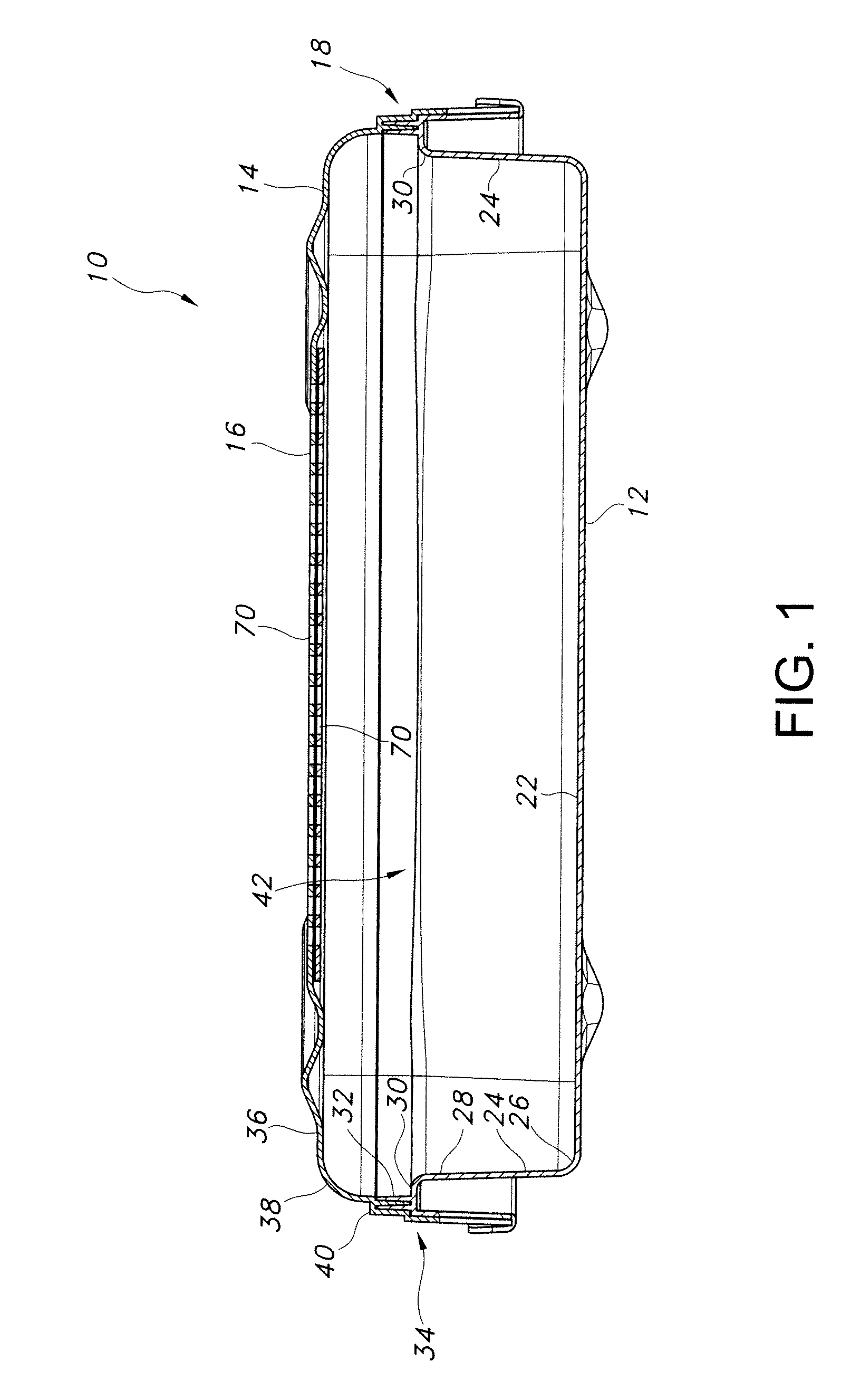
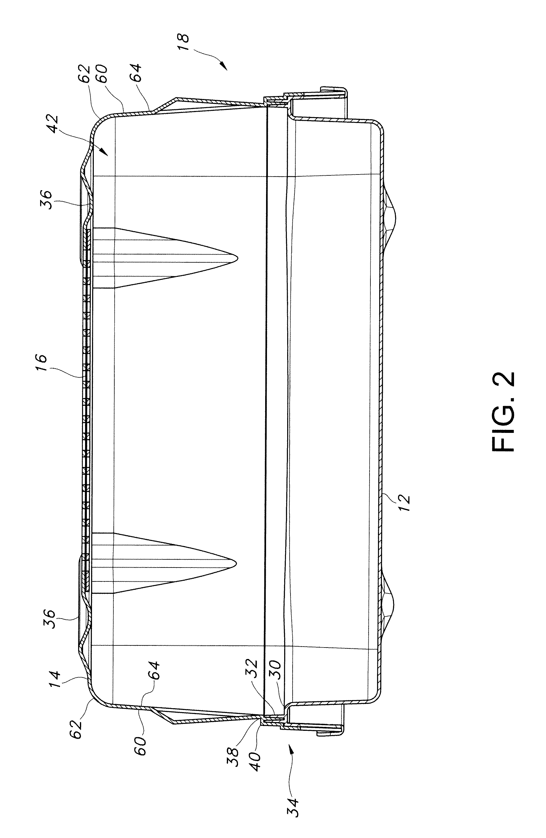
[0058]Referring now to FIG. 1, there is illustrated in cross-sectional view an exe...


PUM

PropertyMeasurementUnit
melting pointaaaaaaaaaa
temperaturesaaaaaaaaaa

Abstract

A non-reusable, locking container for sterilizing and storing surgical materials and presenting surgical materials in a sterilized condition. The non-reusable, locking sterilization container includes a tray, a lid, a permeable filter, a non-reusable lock and a frangible release that limit the container to only a single sterilization cycle or single use.

Description

[0001]This application is a continuation-in-part of, and claims priority to, U.S. Ser. No. 12 / 317,657 filed Dec. 24, 2008 now U.S. Pat. No. 7,942,264 entitled “Sterilization Container With Peel Top” by Steven Scott Friderich et al., which is hereby incorporated by reference for all purposes.BACKGROUND[0002]Sterilization of items used in medical procedures is vital to minimizing the spread of harmful and infectious microbes to patients. Typically, the items used in medical procedures are wrapped with a sterilization wrap made of a gas permeable material or placed in a reusable vented rigid sterilization container. These sterilization wraps or sterilization containers preserve sterility of the items contained therein, as well as the interior portion of these wraps or containers, after the wraps or containers and their respective contents have been channeled through a sterilization process. During a typical sterilization process, the sterilization wraps or vented rigid sterilization co...

Claims


Application Information

Patent Timeline
Patent Type & Authority Patents(United States)
IPC IPC(8): A61B17/06B65D83/10B65D17/34E05B39/02B65D17/32A61L2/00
CPCA61B2019/0245A61B2019/0219A61B2019/4873A61L2/26A61B2019/0239A61B19/0271A61B2019/0272A61B2019/307B65B55/027A61B19/026A61B2019/0213A61B2019/0277Y10T292/48Y10T292/1095A61B50/30A61B50/33A61B50/34A61B2050/006A61B2050/0065A61B2050/0083A61B2050/0089A61B2050/3007A61B2090/037A61B2090/0814
Inventor CESA, JOSEPH A.CLARK, LAUREEN C.CLAY, JOHN K.FRIDERICH, STEVEN SCOTTGORMAN, SEAN P.HERNANDEZ, DAVIDO'CONNOR, DENISE E.SCHWARZ, CORINNASMITH, TARA DENISESTARKEY, JAMES TROYSTERLING, DANIEL P.
Owner O&M HALYARD INC
Why Eureka
Try Eureka