Variable bitrate equipment

a bitrate equipment and variable technology, applied in the field of communication networks, can solve problems such as significant and expensive modifications, reduced signal quality, compatibility problems with existing routers,

Active Publication Date: 2014-01-07
RPX CORP
View PDF21 Cites 9 Cited by
  • Summary
  • Abstract
  • Description
  • Claims
  • Application Information

AI Technical Summary

Benefits of technology

[0003]It is therefore an object of the present invention to overcome the above cited drawbacks of the state of the art and provide a method allowing to aggregate a variable number of input low bitrate signals into an output signal with a variable high bitrate without requiring important modifications in the network design.

Problems solved by technology

Thus, useless signals are transmitted which maximizes the required amount of energy and may lead to a reduced signal quality.
However, such solution requires significant and expensive modifications and may lead to compatibility issues with existing routers.

Method used


Image

  • Variable bitrate equipment
  • Variable bitrate equipment
  • Variable bitrate equipment

Examples


Embodiment Construction

[0030]As used herein, the term “active input” refers to an input receiving data signals;

[0031]As used herein, the term “Gb / s” refers to the unit gigabit per second;

[0032]As used herein, the term “GHz” refers to the unit gigahertz;

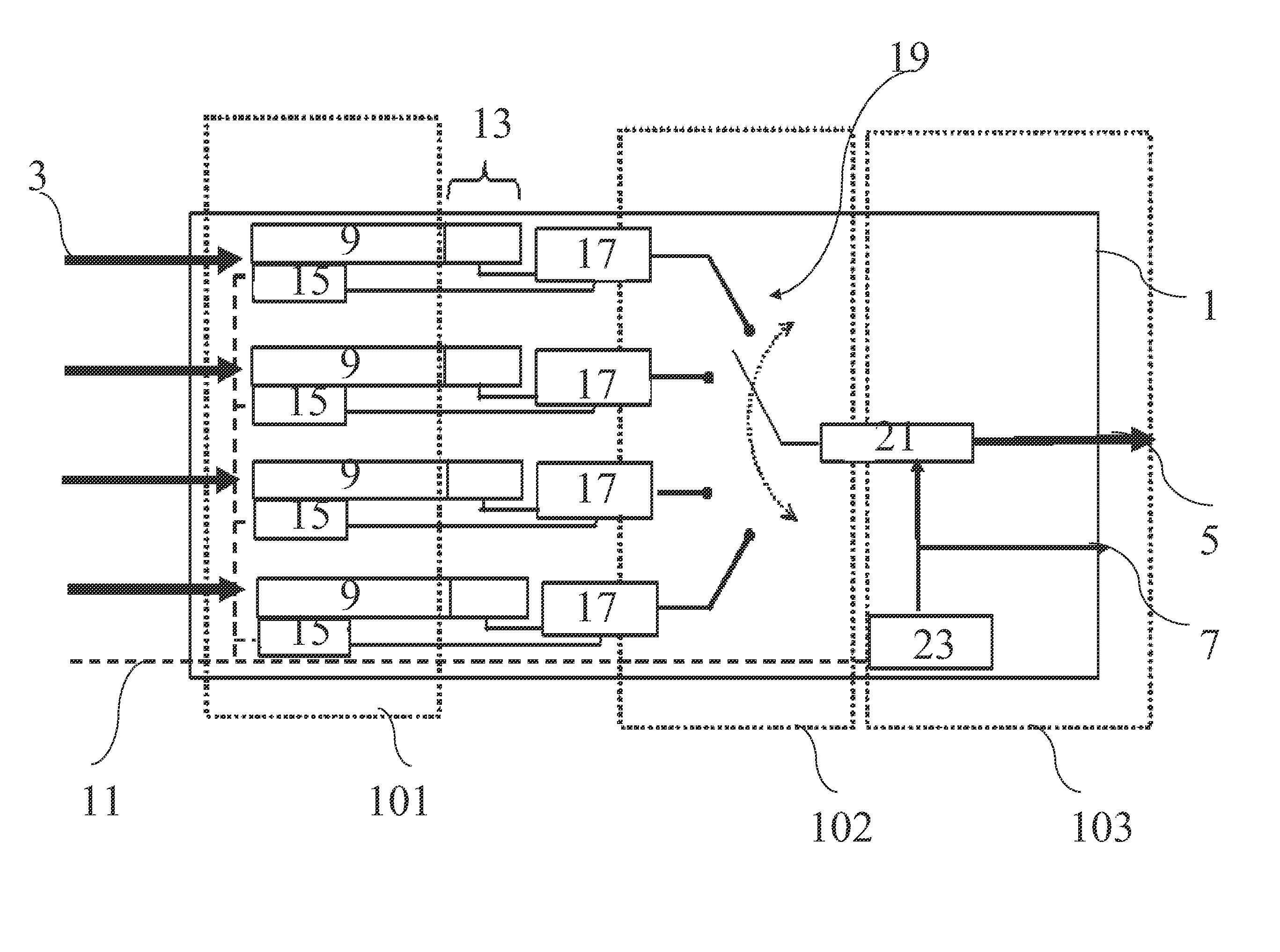
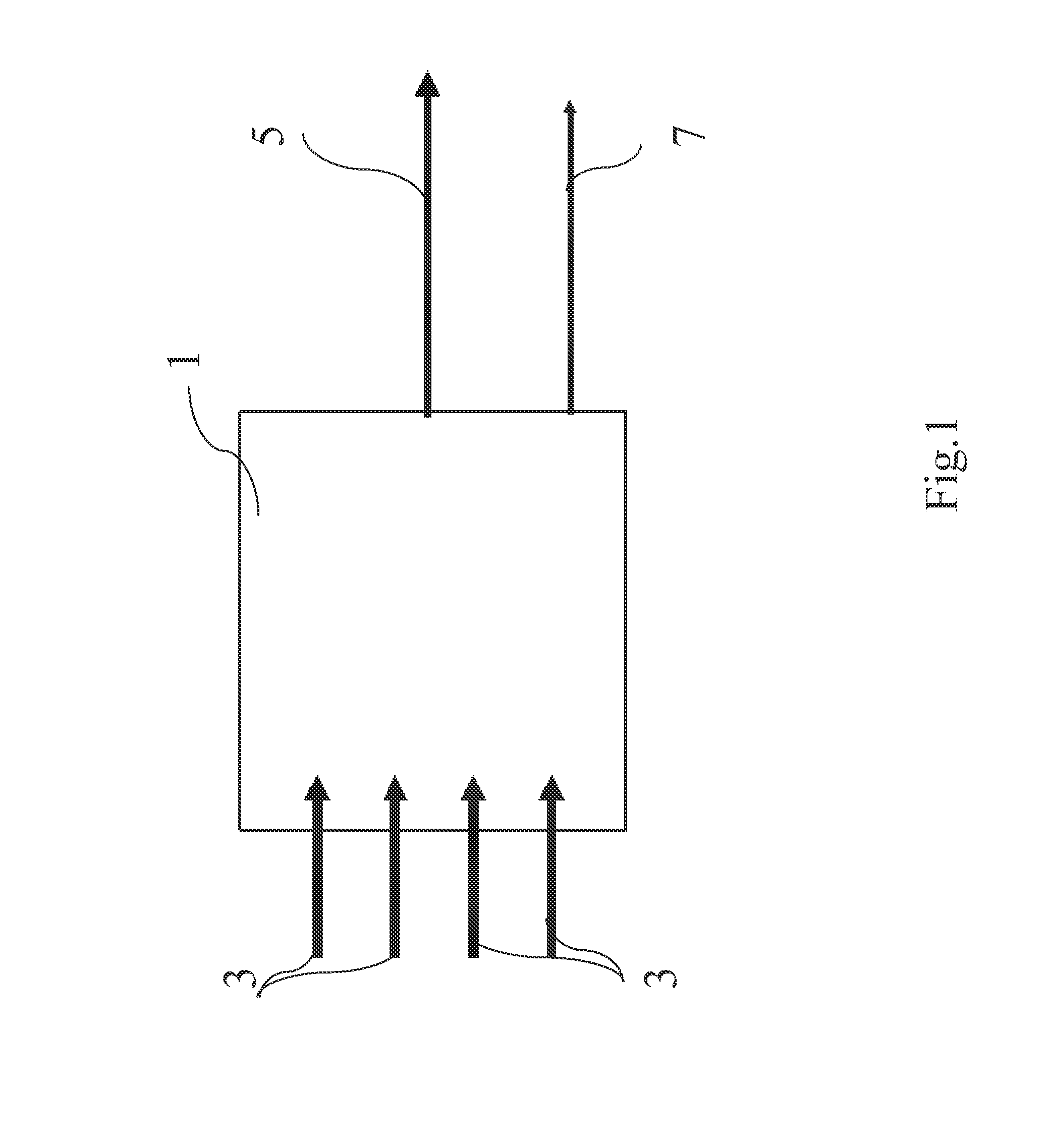
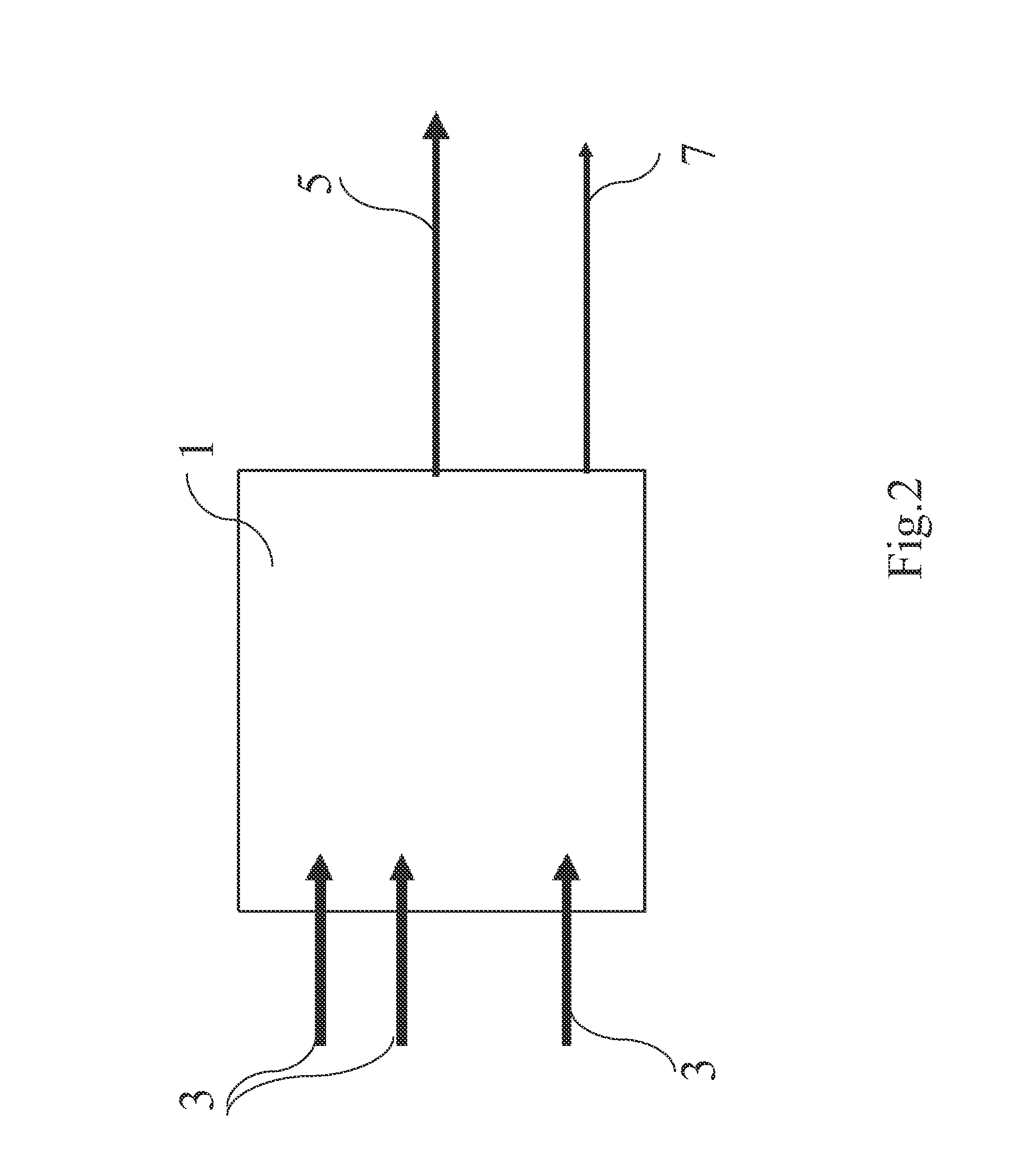
[0033]An embodiment of the present invention refers to a concentrator or transmission system 1 as described in FIG. 1 allowing to aggregate the signals received on a plurality of parallel input channels 3 onto a serial output channel 5 having a bitrate equal to the sum of the bitrates of the input channels 3. In FIG. 1, the transmission system comprises four input channels 3 having each a 10 Gb / s bitrate such that the output channel 5 has a 40 Gb / s bitrate. Moreover, a clock signal 7 corresponding to the bitrate of the output channel (40 GHz in the present case) is provided. Besides, if only three of the input channels 3 are active as represented in FIG. 2, the bitrate of the output channel 5 becomes 30 Gb / s corresponding to a clock signal 7 of 30 GHz. In a...


PUM


Abstract

The present invention refers to a signal concentrator comprising:a parallel to serial conversion device comprising a plurality of parallel inputs and a serial output,a control unit comprising detection means adapted for detecting the activity of said plurality of parallel inputs of said parallel to serial conversion device, indication means adapted for indicating the active parallel inputs to the parallel to serial conversion device and controlling means adapted for setting an operating bitrate of the serial output in function of said activity of said plurality of parallel inputs.

Description

BACKGROUND OF THE INVENTION[0001]The present invention relates to the field of communication networks and in particular to dynamic networks with bitrate agility.[0002]Current communication networks comprises different types of transmission links having different bitrates. Thus, in order to reduce transmission costs while providing enhanced services, an idea is to aggregate a plurality of low bitrate data streams into a high bitrate data stream for high speed communications.In the state of the art, concentrators allowing to aggregate several signals are known but the bitrate of the output transmission link is always the same whatever the number of received signals. Indeed, in case of inactive inputs, bit padding is achieved in order to compensate for the missing signal.Thus, useless signals are transmitted which maximizes the required amount of energy and may lead to a reduced signal quality.Besides, another solution for adapting the bitrate of the output port of a concentrator is to...

Claims


Application Information

Patent Timeline
Patent Type & Authority Patents(United States)
IPC IPC(8): H03M7/20
CPCH04J3/1682H04L12/28H04L65/00
Inventor RIVAL, OLIVIERMOREA, ANNALISA
Owner RPX CORP
Why Eureka
Try Eureka