
Method and system for generating design constraints

a technology of design constraints and constraints, applied in the field of electronic circuit design, can solve the problems of increasing the complexity of the design, generating timing exceptions for the entire design without considering the impact of the exception on the quality, and being susceptible to errors, etc., to achieve the effect of reducing the correctness and consistency of constraints, reducing runtime, and eliminating the problem of errors

Active Publication Date: 2014-01-07
CADENCE DESIGN SYST INC
View PDF41 Cites 9 Cited by
  • Summary
  • Abstract
  • Description
  • Claims
  • Application Information

AI Technical Summary

Benefits of technology

The tim ing constraint method described in this patent makes it easier and more accurate to create and use constraints in a computer-based system. This can improve the quality of results and reduce the time needed for the process.

Problems solved by technology

There are many challenges in this design process.
First, the design constraints are developed manually and therefore are susceptible to errors.
Second, as the complexity of the designs increases, the design may be partitioned into multiple blocks.
As a result, the design constraints also need to be partitioned accordingly.
Maintaining correctness and consistency in the design constraints between block boundaries and between block constraints and the top-level, full-chip constraints become a challenge.
For that matter, integrating block level design constraints for various IP cores developed at the block level by block owners, into top-level, full-chip design constraints for global timing analysis and synthesis, also becomes a challenge.
Moreover, there might be bugs in the design which cause inconsistencies between functional behavior of a design and a design constraint specification given in a format, such as Cadence Common Timing Engine (CTE) Design Constraint Format, Synopsys Design Constraint (SDC) Format, and / or various other design constraint specifications).
Design constraints may include timing constraints, such as clock characterization, delay specifications, and timing exceptions, such as false path and multi-cycle path exceptions.
Furthermore, it generated timing exceptions for the entire design without considering the exception's impact on the quality of the results downstream.
Unfortunately, in some instances, the constraints are developed manually.
With increasing design size and complexity, these design constraints also increase in number and complexity.
Incorrect and / or incomplete constraints may lead to sub-optimal designs, in terms of area, timing and / or power, or even worse, may lead to silicon failures.

Method used


Image

  • Method and system for generating design constraints
  • Method and system for generating design constraints
  • Method and system for generating design constraints

Examples


Embodiment Construction

[0026]Various embodiments of the present invention are described hereinafter with reference to the drawings. It should be noted that the drawings are not drawn to scale and that elements of similar structures or functions are represented by like reference numerals throughout the drawings.

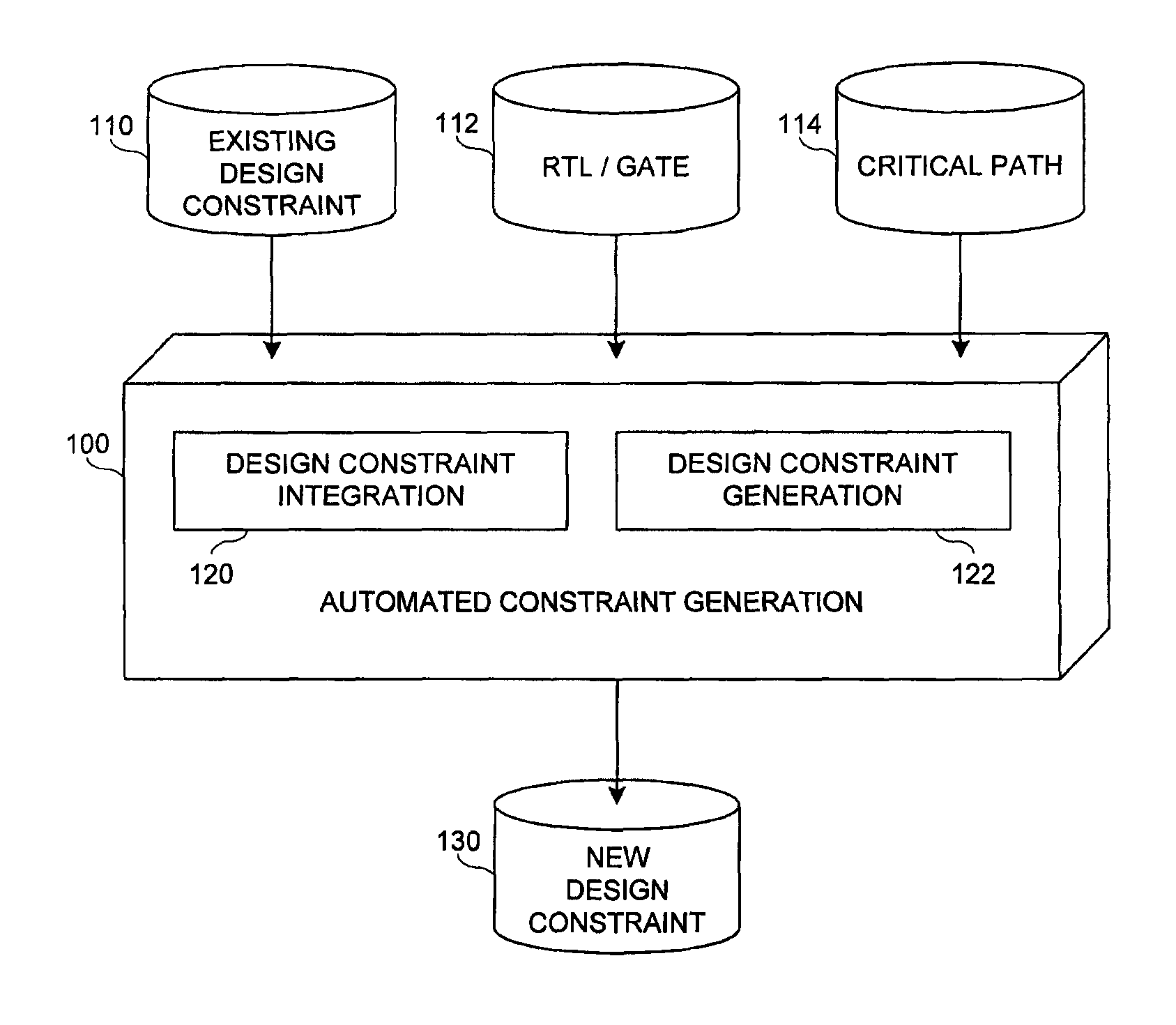
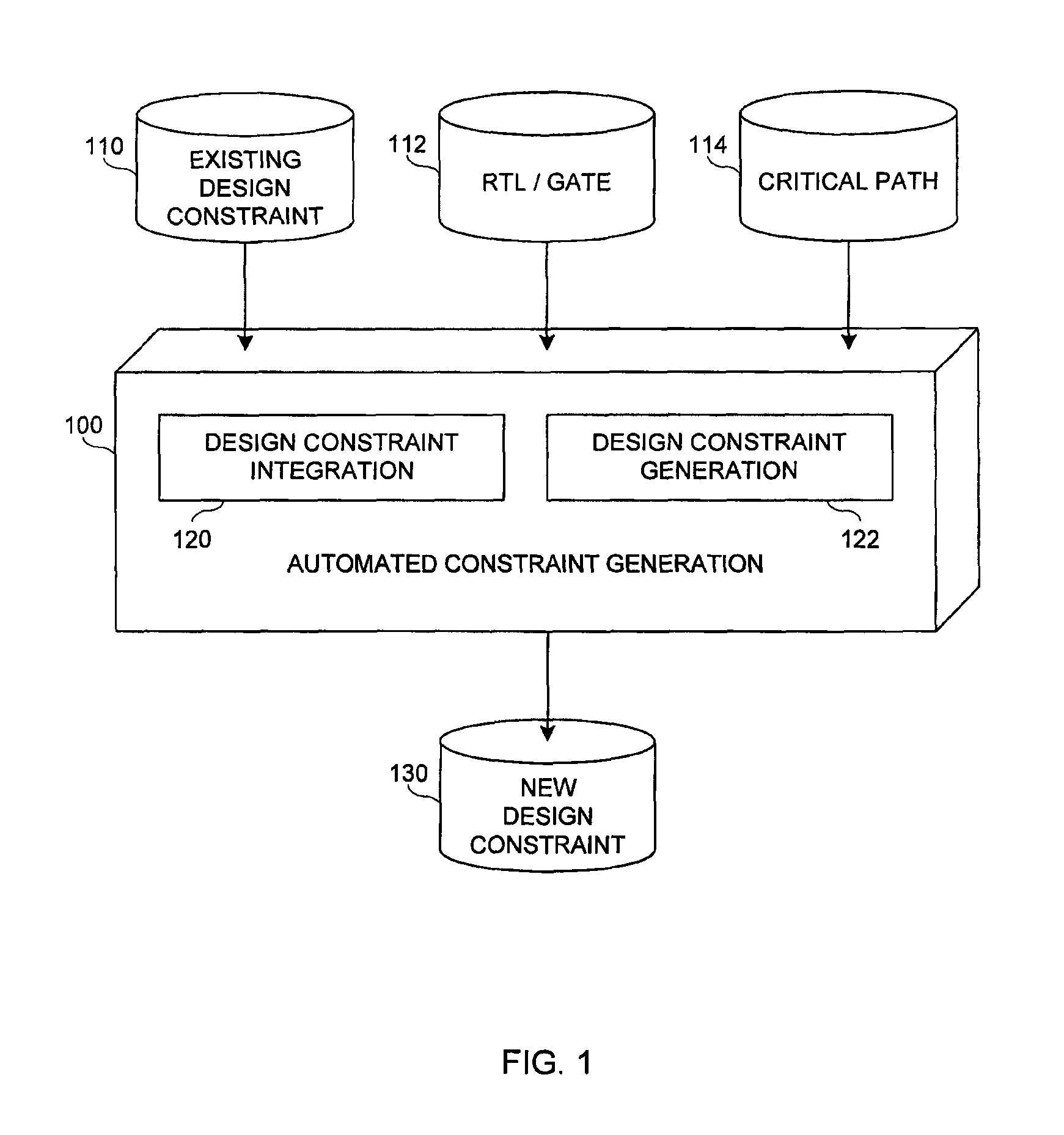
[0027]In one embodiment, timing constraint creation methodology provides a comprehensive automated constraint creation flow that generates timing constraints that are proven correct and consistent. One contribution of this methodology includes a new design constraint integration technique that provides methodical means for integrating sub-block constraints so as to maintain correctness and consistency of top-level constraints. Another contribution of this methodology includes techniques for automatic design exploration and use of formal verification methods to generate and prove timing constraints by systematic means.

[0028]In greater detail herein, topics that will be discussed include design constr...


PUM


Abstract

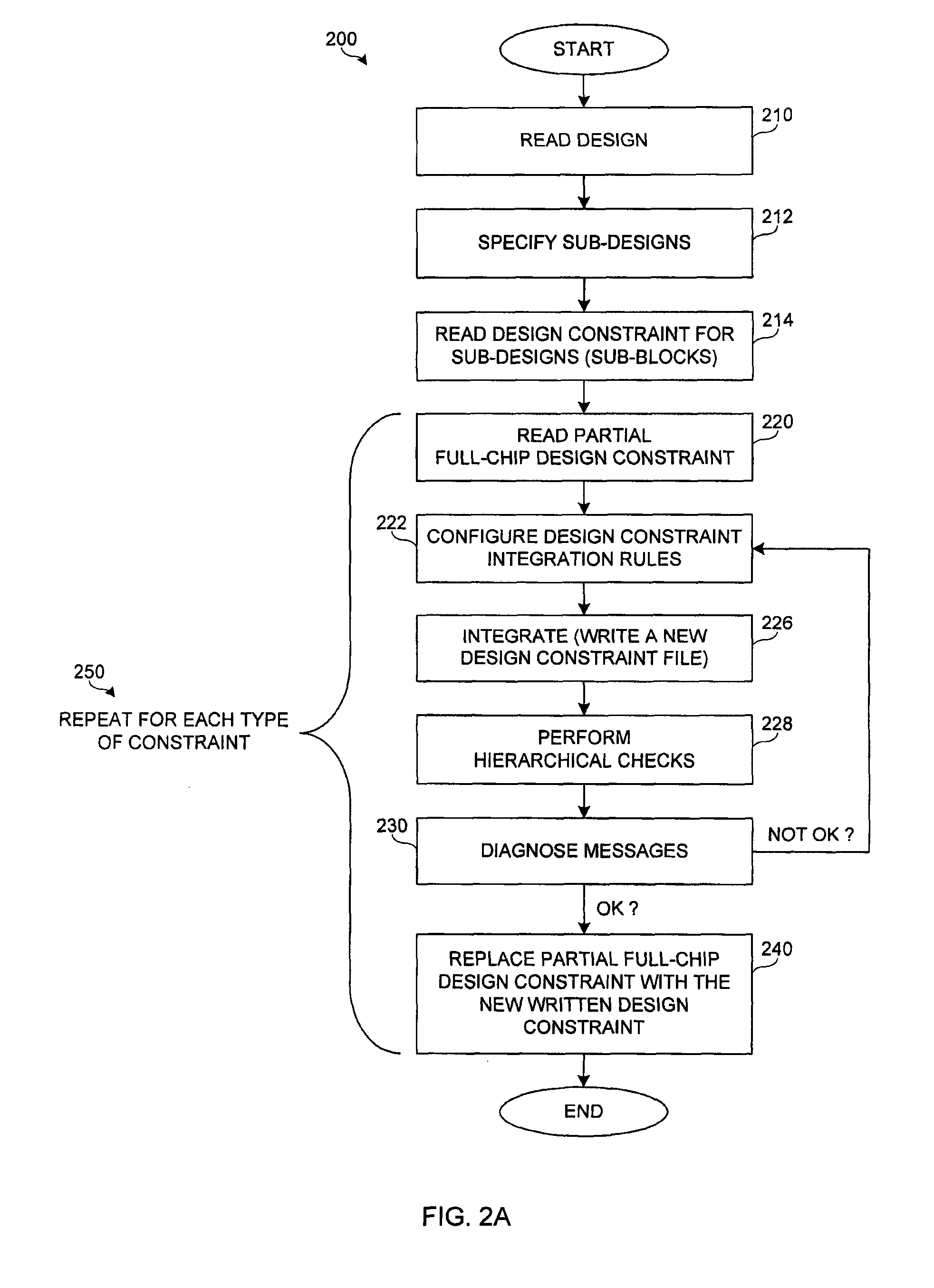
A method and system for generating design constraints for an electronic circuit design is disclosed. The method and system include reading a design description and an existing design constraint file, configuring design constraint integration rules, writing a new design constraint file, evaluating results of the new design constraint file, and replacing existing design constraint file with the new design constraint file.

Description

CROSS-REFERENCE TO RELATED APPLICATIONS[0001]This application is a continuation of U.S. application Ser. No. 11 / 952,798, now U.S. Pat. No. 7,962,886, filed on Dec. 7, 2007, which claims the benefit of U.S. Provisional Application No. 60 / 873,886 filed on Dec. 8, 2006, both of the above applications are hereby incorporated by reference in their entireties for all purposes.BACKGROUND[0002]1. Field[0003]The field of the present invention relates to electronic circuit design and, in particular, to generating design constraints for electronic circuit designs.[0004]2. Description of Related Art[0005]Typically, a design flow at various levels of design abstraction involves specifying design constraints while different synthesis tools optimize the design around these constraints. In case of timing constraints, after synthesis, a static timing analysis is used to verify whether a design is meeting the timing budget. If this is not the case, the static timing analysis produces a critical path ...

Claims


Application Information

Patent Timeline
Patent Type & Authority Patents(United States)
IPC IPC(8): G06F17/50
CPCG06F17/5045G06F30/30
Inventor PANDEY, MANISHGLUSMAN, MARCALOKRSTIC, ANGELAHSIEH, YEE-WINGLIN, ANDY
Owner CADENCE DESIGN SYST INC
Learn More