Traction assembly

a technology of traction assemblies and components, applied in the direction of driving belts, belts/chains/gearrings, mechanical equipment, etc., can solve the problem that the traction assembly may operate less efficiently

Inactive Publication Date: 2014-01-21
BESSETTE ROBERT
View PDF22 Cites 15 Cited by
  • Summary
  • Abstract
  • Description
  • Claims
  • Application Information

AI Technical Summary

Benefits of technology

[0007]A traction assembly in accordance with the principles of the present invention generally mitigates the aforementioned shortcoming of prior art traction assemblies by allowing the weight of the vehicle to be substantially automatically transferred on the trailing portion of the traction assembly with respect to the direction of movement of vehicle.
[0008]Such a weight transfer generally allows the leading portion of the traction assembly to rise or climb over the ground surface, thereby preventing the traction assembly from diving or digging into the ground surface, particularly when the ground surface is soft.
[0015]In that sense, and in accordance with the principles of the present invention, the forward and rearward pivotal movements of the support arm allows the weight of the vehicle to be substantially transferred on the trailing portion of the support frame when the vehicle operates in a particular direction.
[0016]Hence, when the vehicle is moving forwardly, the support arm will pivot rearwardly such as to transfer the weight of the vehicle on the trailing portion of the support frame which is the rear portion in this case. This will cause the trailing portion of the support frame to apply more pressure on the ground surface than the leading portion, i.e. front portion. This, in turn, will allow the leading portion to rise with respect to the trailing portion, thereby forming a more effective approaching angle.
[0017]When the vehicle is moving rearwardly, the support arm will pivot forwardly such as to transfer the weight of the vehicle on the trailing portion of the support frame, now the front portion. This will cause the trailing portion of the support frame to apply more pressure on the ground surface than the leading portion, now the rear portion. This, in turn, will allow the leading portion to rise with respect to the trailing portion, thereby forming a more effective approaching angle.
[0020]The skill addressee will thus understand that the pivotal movements of the support arm automatically changes the geometry of the traction assembly such as to shift the weight of the vehicle on the trailing portion of the support frame and such as to change the distribution of the pressure applied on the ground. The pivotal movements of the support arm also improve the approaching angle of the traction assembly when the vehicle travels in a forward or a reverse direction as the weight transfer over the trailing portion allows the leading portion to rise.

Problems solved by technology

Still, despite all the developments in the field of traction assemblies, there remain some problems.
However, when the vehicle operates in a backward direction, the traction assemblies may operate less efficiently.

Method used


Image

  • Traction assembly
  • Traction assembly
  • Traction assembly

Examples


Embodiment Construction

[0031]A novel traction assembly will be described hereinafter. Although the invention is described in terms of specific illustrative embodiments, it is to be understood that the embodiments described herein are by way of example only and that the scope of the invention is not intended to be limited thereby.

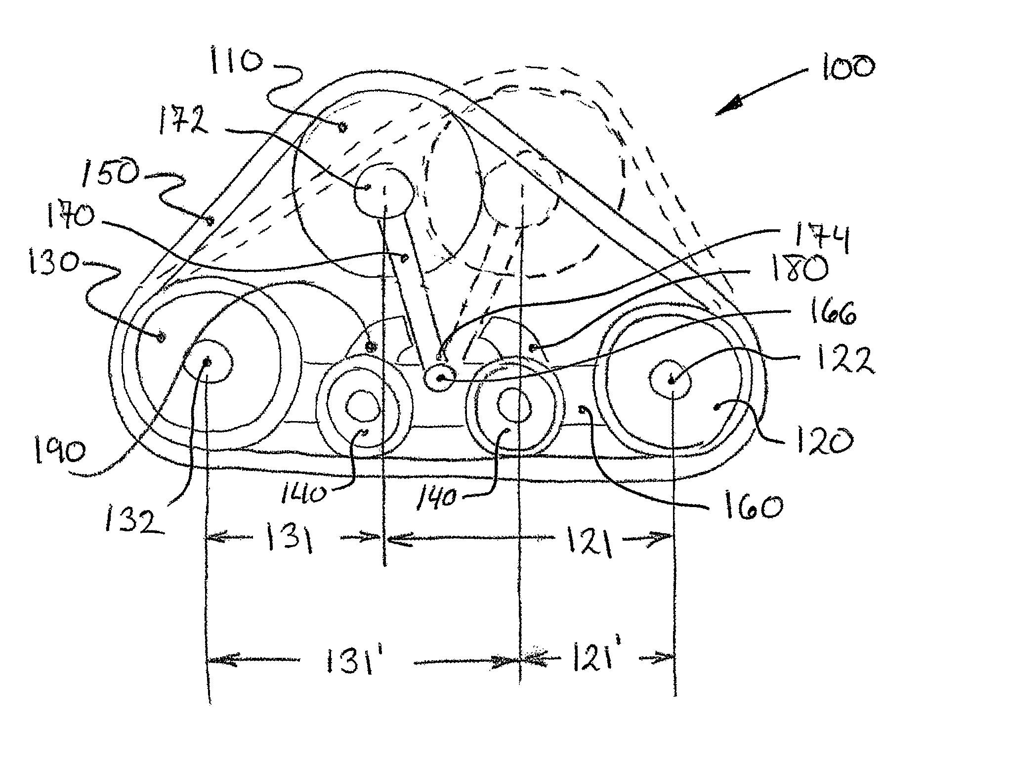
[0032]Referring first to FIGS. 4-6 and 8, a traction assembly 100 in accordance with the principles of the present invention is shown. The traction assembly 100 is generally configured to be used as a wheel replacement on a typically wheeled vehicle 10 or equipment.

[0033]As it will be described and explained in more details below, the traction assembly 100 allows the weight of the vehicle 10 to be substantially automatically transferred on the trailing portion of the support frame of the traction assembly 100 with respect to the direction of the movement of the vehicle 10.

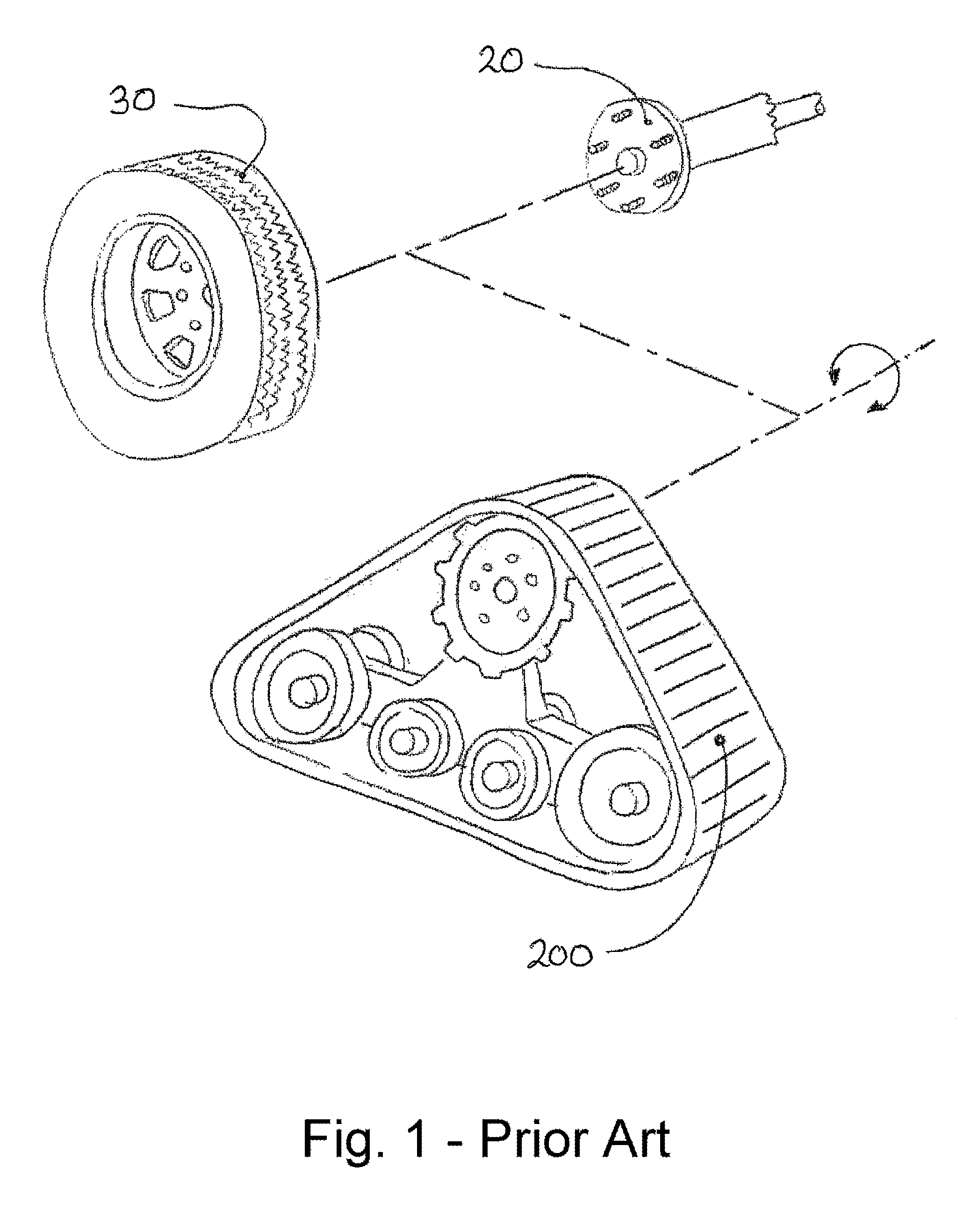
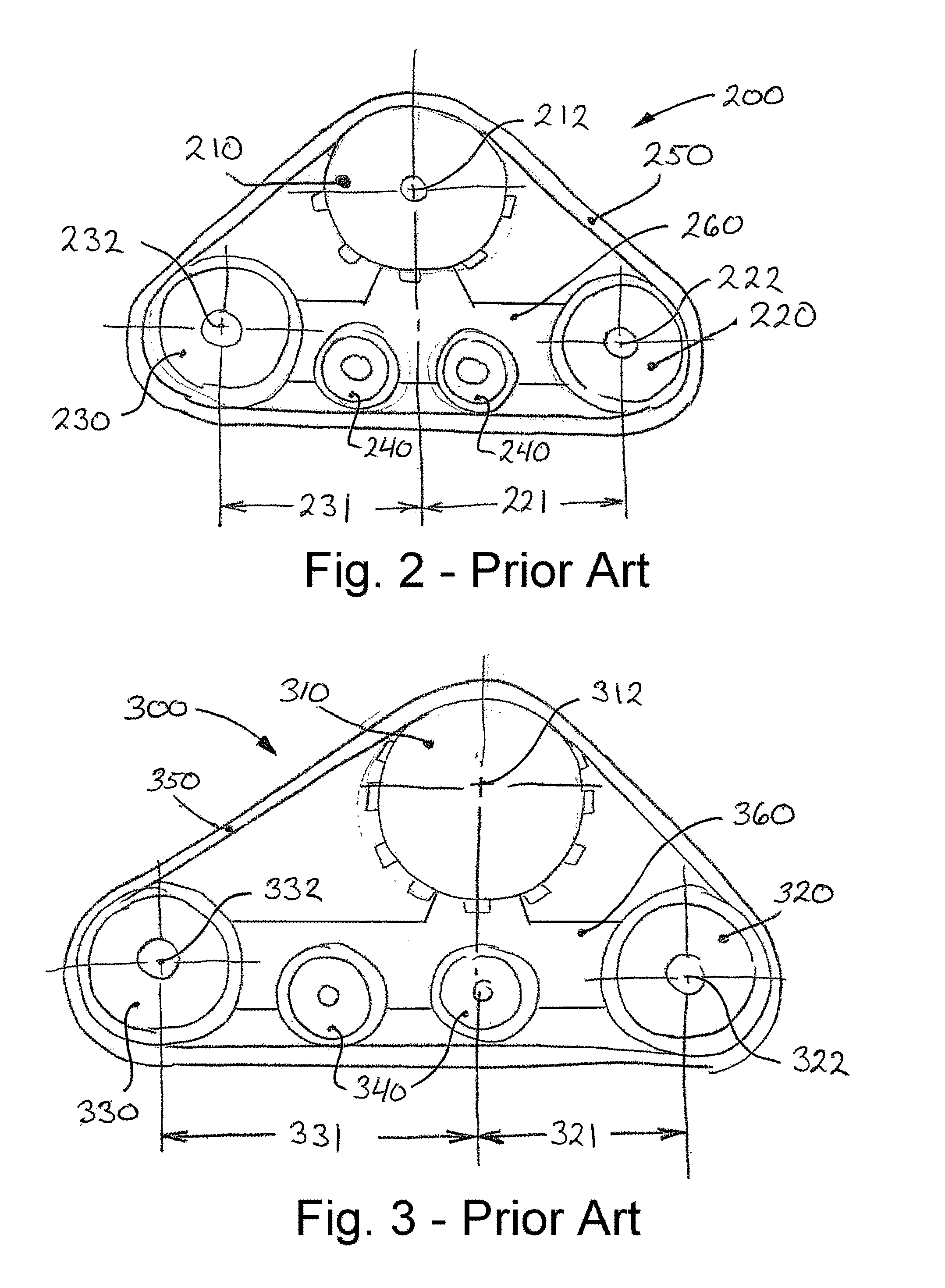
[0034]Referring now to FIG. 1 and particularly to FIGS. 2 and 3, in most existing traction assemblies, the geo...


PUM


Abstract

A traction assembly for replacing a wheel on a vehicle is disclosed. The traction assembly uses a traction band disposed about a sprocket wheel, idler wheels and road wheels for propulsion. The idler wheels and road wheels are pivotally mounted to a support frame which is coupled to the sprocket wheel via a support arm. The support arm is pivotally yet non-drivingly connected to the sprocket wheel and is pivotally connected to the support frame. The support arm is able to pivot forwardly and rearwardly, albeit in a limited fashion, with respect to the support frame. Such forward and rearward pivotal movements allow the weight of the vehicle to be transferred on the trailing portion, i.e. either the front or the rear portion, of the support frame depending on the direction of movement of the vehicle, thereby generally preventing the leading portion from diving or digging into the ground.

Description

CROSS-REFERENCE TO RELATED APPLICATIONS[0001]The present patent application claims the benefits of priority of commonly own U.S. Provisional Patent Application No. 61 / 328,252, entitled “Traction Assembly with Anti-Diving System” and filed at the United States Patent and Trademark Office on Apr. 27, 2010, the content of which is incorporated herein by reference.FIELD OF THE INVENTION[0002]The present invention generally relates to traction assemblies and track systems using endless traction band for propulsion. More particularly, the present invention relates to traction assemblies and track systems for replacing wheels on typically wheeled vehicles and / or other equipments.BACKGROUND OF THE INVENTION[0003]Over the years, it has often been found practical to replace the wheels of a wheeled vehicle with traction assemblies which use endless tracks for propulsion.[0004]Traction assemblies are known to generally increase the traction and the floatation of vehicles when used over soft ter...

Claims


Application Information

Patent Timeline
Patent Type & Authority Patents(United States)
IPC IPC(8): B62D55/084
CPCB62D55/084B62D55/14B62D55/04
Inventor BESSETTE, ROBERT
Owner BESSETTE ROBERT
Why Eureka
Try Eureka