
Inter-cluster communications technique for event and health status communications

Inactive Publication Date: 2014-01-21
INT BUSINESS MASCH CORP
View PDF43 Cites 12 Cited by
  • Summary
  • Abstract
  • Description
  • Claims
  • Application Information

AI Technical Summary

Problems solved by technology

However, the event communications and health status monitoring are typically performed only among nodes in a single cluster.

Method used


Image

  • Inter-cluster communications technique for event and health status communications
  • Inter-cluster communications technique for event and health status communications
  • Inter-cluster communications technique for event and health status communications

Examples


Embodiment Construction

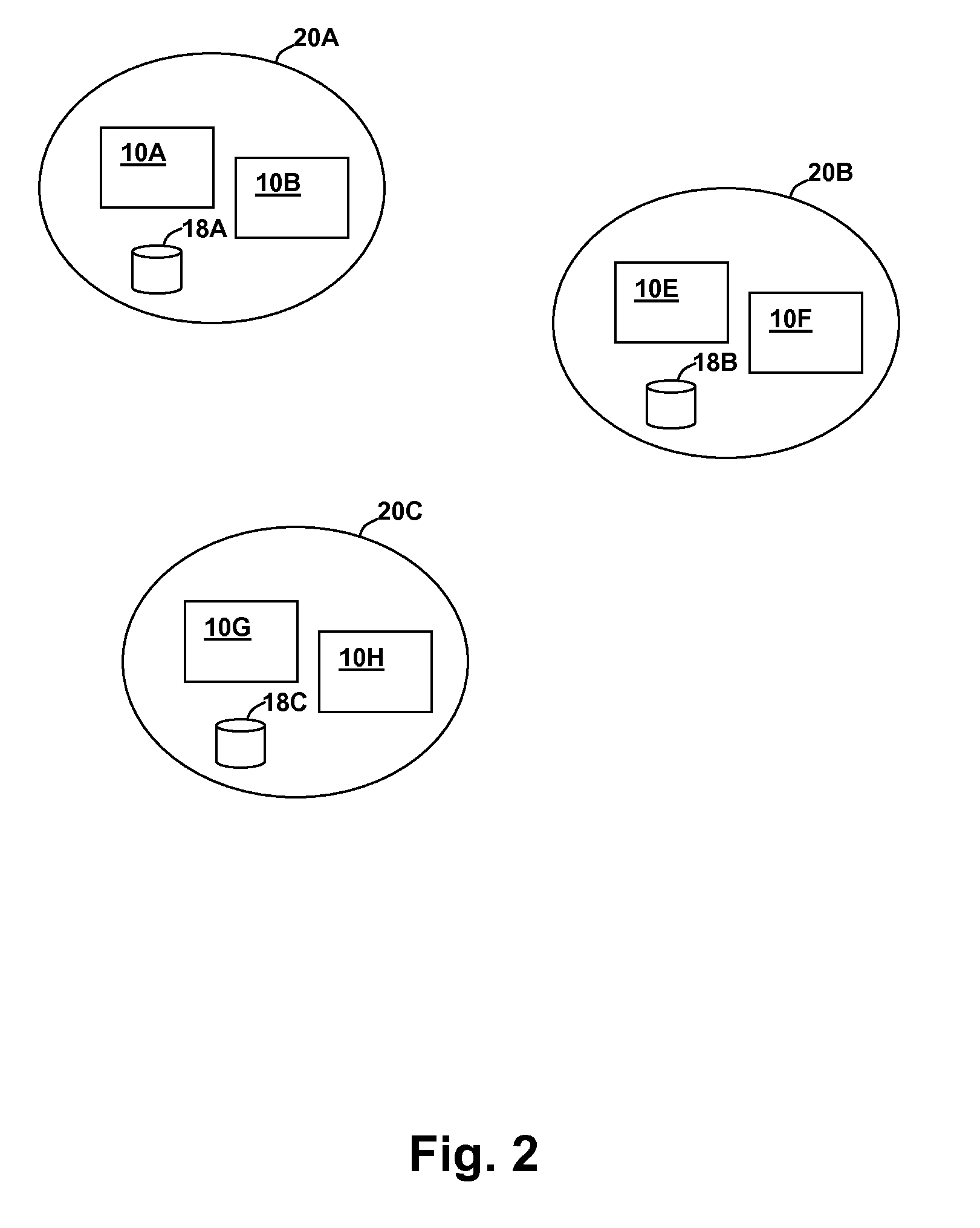
[0015]The present invention encompasses techniques for communication between nodes in different clusters of nodes within distributed computing systems. In particular, embodiments of the invention provide for communication of node status changes between different clusters that may be in different geographical locations and on different local area networks (LANs), and communication of other inter-node messaging, such as event messages. Gateway node(s) in each cluster communicate status changes such as node down / up events for their cluster to the remote cluster(s), providing a low bandwidth usage status monitoring.

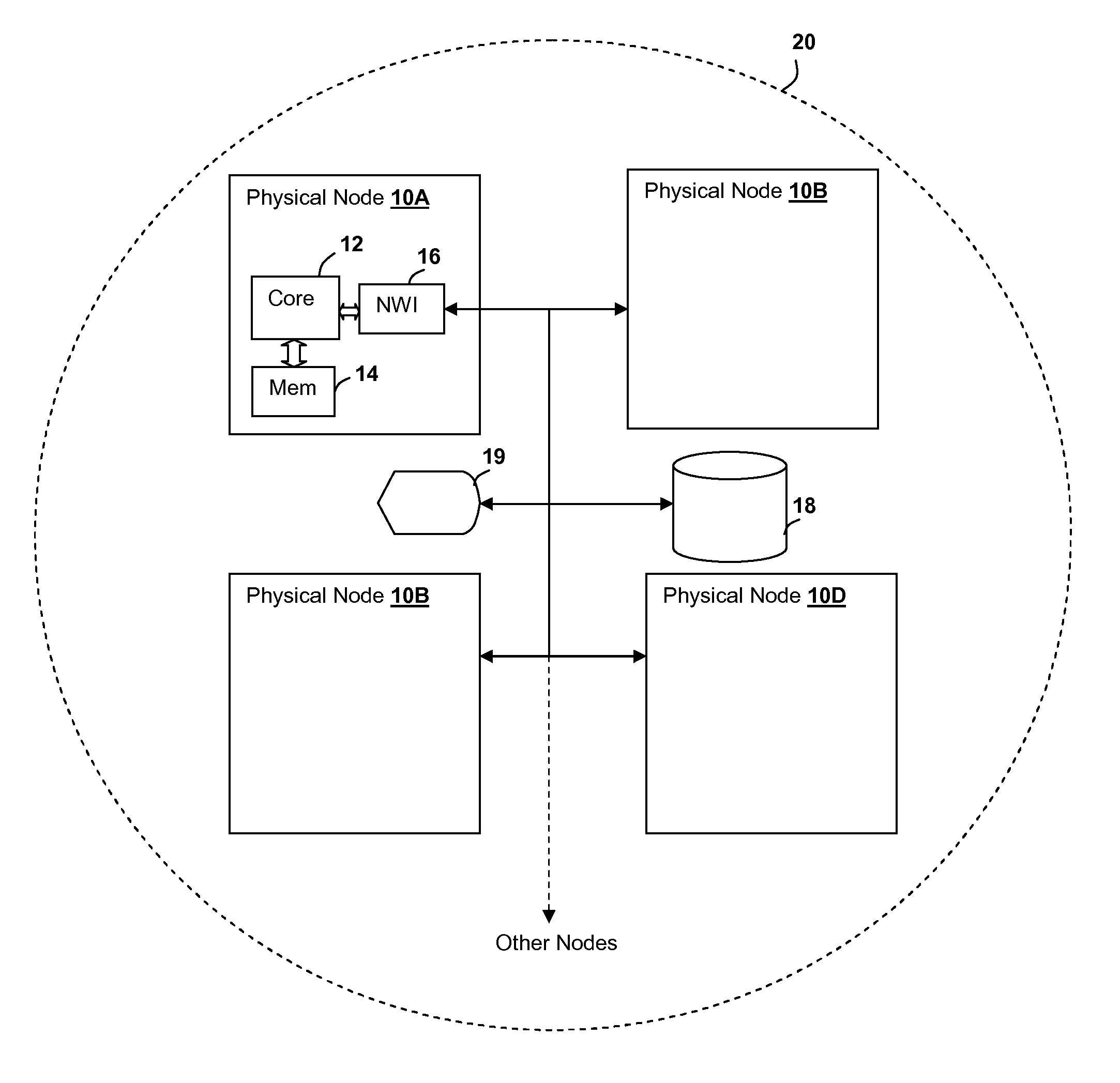
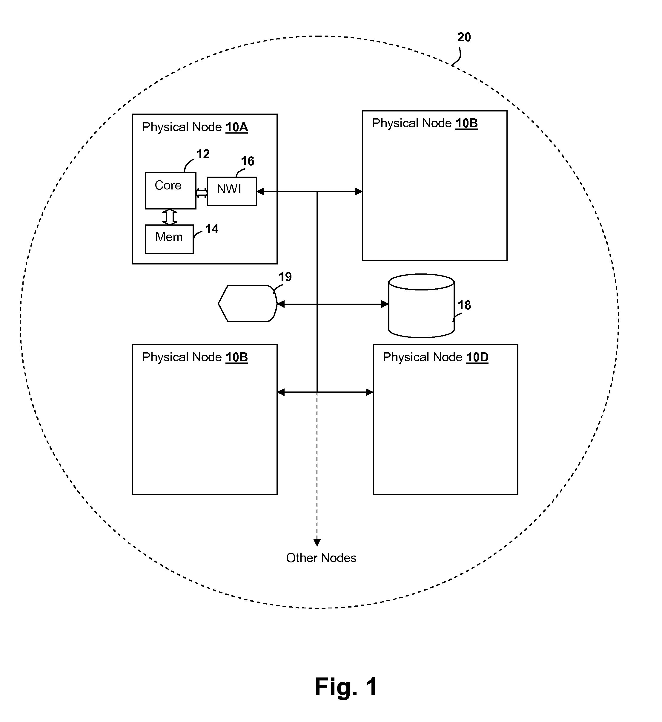
[0016]Referring now to FIG. 1, a cluster 20 within a distributed computer system in accordance with an embodiment of the present invention is shown. A first physical processing node 10A includes a processor core 12 coupled to a memory 14 that stores program instructions for execution by processor 12. The program instructions include program instructions forming computer progr...


PUM


Abstract

Communication between clusters of processing nodes is initiated by designating a link layer address and a target node name in a remote cluster. The link layer address is transmitted to the target node via a regular network transmission. The link layer address is stored locally in each cluster and the nodes in each cluster are signaled that a configuration change has been made, so that gateway nodes in the clusters can obtain the link layer address to use for subsequent communications with the other cluster, such as event notifications of node status changes.

Description

BACKGROUND[0001]1. Field of the Invention[0002]The present invention is related to communications between nodes in different clusters in large-scale distributed computer systems, and more specifically to a technique for inter-cluster communication that shares a link layer address between clusters.[0003]2. Description of Related Art[0004]In large-scale distributed computer systems, such as those using distributed software models to perform tasks, multiple nodes provide independent execution of sub-tasks. The nodes are typically organized into clusters in order to perform specific tasks and / or as a physical organization of a processing system, for example, clustering by processor affinity. In order to keep such a system operational, and further, to provide indication of events occurring at one node that either require a reaction from another node or indicate to the other node that either an erroneous operating condition has occurred, or that a phase of processing is complete. In parti...

Claims


Application Information

Patent Timeline
Patent Type & Authority Patents(United States)
IPC IPC(8): H04L12/28
CPCH04L61/6022H04L61/103H04L2101/622
Inventor GANAPATHY, ARUNACHALAMMISHRA, RAJEEVRUSSELL, LANCE W.VADDAGIRI, MURALI
Owner INT BUSINESS MASCH CORP
Learn More