Communication connector system for a weapon

a technology of communication connectors and weapons, which is applied in the direction of firing/trigger mechanisms, cartridge extractors, coupling contact members, etc., can solve the problems of not being compatible with existing parts, unable to connect the electronics in the lower part of the weapon with the electronics in the upper rail, and prone to catch or snag wires

Inactive Publication Date: 2014-01-28
TE CONNECTIVITY CORP
View PDF28 Cites 30 Cited by
  • Summary
  • Abstract
  • Description
  • Claims
  • Application Information

AI Technical Summary

Problems solved by technology

Connecting the electronics in the lower part of the weapon with the electronics in the upper rail has heretofore proven difficult.
The wires tend to catch or snag or are exposed to be easily damaged, which is problematic.
Other systems route wires internally, however the upper and lower receivers need to be completely redesigned, and thus are not compatible with existing parts.
Additionally, the weapons are often disassembled, such as for cleaning, and having the internal wiring makes disassembly difficult.

Method used


Image

  • Communication connector system for a weapon
  • Communication connector system for a weapon
  • Communication connector system for a weapon

Examples


Embodiment Construction

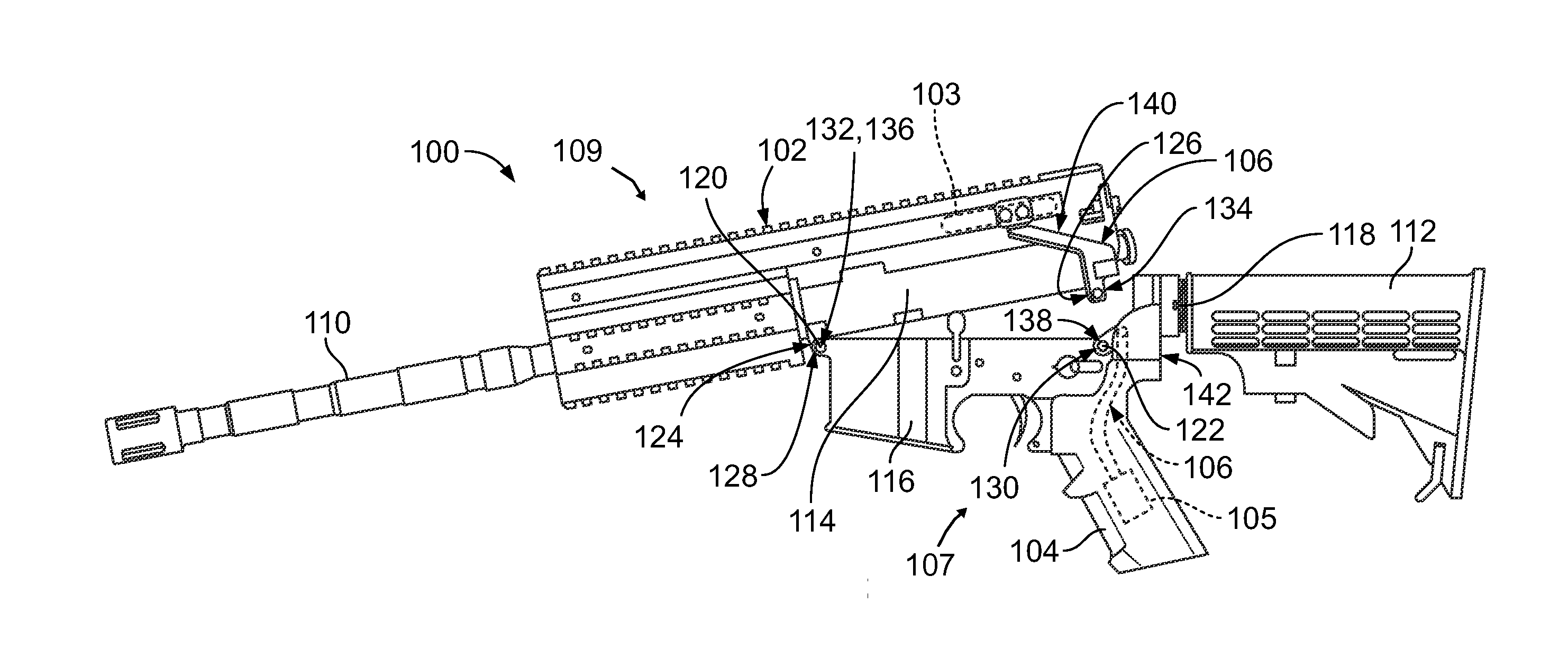
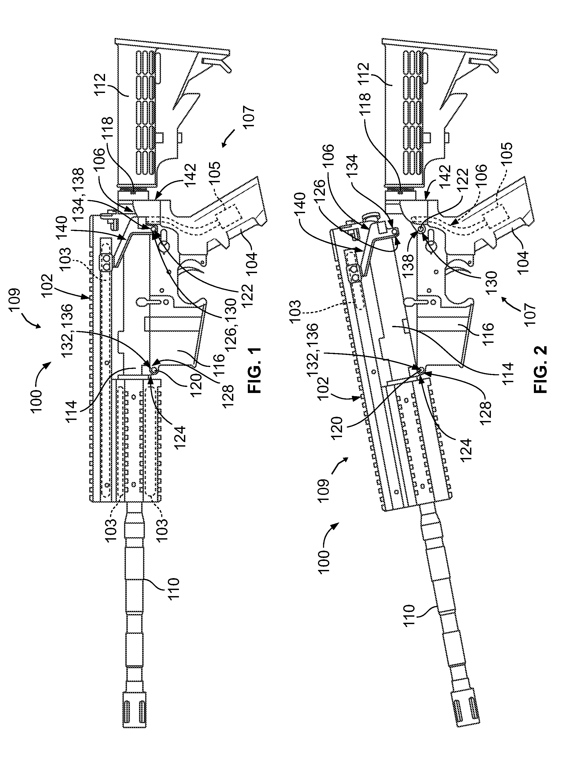
[0017]FIG. 1 is a side view of a weapon 100 formed in accordance with an exemplary embodiment and shown in a closed state. FIG. 2 is a side view of the weapon 100 in an open state. In the illustrated embodiment, the weapon 100 is an AR-15 style weapon, however other types of weapons may be used in alternative embodiments.

[0018]In an exemplary embodiment, the weapon 100 is of a type that includes a rail 102 having electronics 103 therein and a base 107 having electronics 105 therein. The base 107 includes a hand grip 104, a lower receiver 116 and a butt stock 112. The electronics 105 may be housed in any of the hand grip 104, the lower receiver 116 and / or the butt stock 112. The base may include other components of the weapon 100. The weapon 100 includes a communication connector system 106 that communicatively connects the electronics 105 of the base 107 with the electronics 103 associated with the rail 102. The electronics may be electrically connected, optically connected, inducti...


PUM


Abstract

A communication connector system for a weapon having an upper receiver at an upper part of the weapon with electronics associated with the upper receiver and a base at a lower part of the weapon with a lower receiver and a hand grip and that houses electronics and with the upper receiver rotatably coupled to the lower receiver and movable between a closed position and an open position includes an upper connector assembly configured to be coupled to the upper receiver. The upper connector assembly has an upper connector being configured to be communicatively connected to the electronics in the upper receiver. The upper connector has a mating interface. A lower connector assembly has a lower connector that is configured to be communicatively connected to the electronics in the base of the weapon. The lower connector is configured to be mounted to the hand grip. The lower connector has a mating interface configured to be mated with the mating interface of the upper connector when the upper receiver is in the closed position. The mating interfaces are physically separable from one another so the upper receiver is able to move to the open position.

Description

BACKGROUND OF THE INVENTION[0001]The subject matter herein relates generally to communication connector systems for weapons.[0002]Weapons, such as AR-15s, M4's, M-16's, and others, include a rail having electronics mounted to or within the upper rail. The upper rail may include a laser, night vision scope, camera or other type of electronic that needs power. The electronics may also send or receive data. The weapons typically include electronics, including batteries, in the lower part of the weapon, such as in the butt stock, hand grip, lower receiver, which are communicatively connected to the electronics in the upper rail.[0003]Connecting the electronics in the lower part of the weapon with the electronics in the upper rail has heretofore proven difficult. Some systems use wires along the outside of the gun that interconnect the electronics in the lower part of the weapon with the electronics in the upper rail. The wires tend to catch or snag or are exposed to be easily damaged, w...

Claims


Application Information

Patent Timeline
Patent Type & Authority Patents(United States)
IPC IPC(8): F41A19/00
CPCF41A11/04H01R13/24F41C27/00
Inventor MULFINGER, ROBERT, NEIL
Owner TE CONNECTIVITY CORP
Why Eureka
Try Eureka