Brushless DC motor with bearings

a dc motor and bearing technology, applied in the direction of positive displacement liquid engines, pumps, machines/engines, etc., can solve the problems of compromising bearing performance, real-world designs are less than perfect, and the state of the art is far from per

Active Publication Date: 2014-01-28
RESMED MOTOR TECH
View PDF45 Cites 493 Cited by
  • Summary
  • Abstract
  • Description
  • Claims
  • Application Information

AI Technical Summary

Problems solved by technology

Real world designs are less than perfect and, therefore, compromise bearing performance.
With respect to the first constraint, although the precision of part forming technologies improves continuously, the state of the art is far from perfect.
Furthermore, increased precision usually translates to greater expense, often dissuading a manufacturer from embracing the state of the art processes.
A consequence of multipart housings is that they accumulate unwanted tolerance build-up at each faying or joint surface.
For example, FIG. 8 illustrates a metallic tube T housing bearings B1, B2, and a rotor R supported by the bearings B1, B2 in cantilever fashion to support an impeller I. However, the metallic tube prevents a high speed magnetic rotor from being packaged between the bearings, i.e., an internal rotor design, because magnetic fields cannot effectively cross a metallic barrier without significant loss of flux density and / or increased heat.
Also, there are practical limits to how much mass and length can be cantilevered from a set of high speed bearings.
Therefore, such designs tend to be axially short in length.

Method used


Image

  • Brushless DC motor with bearings
  • Brushless DC motor with bearings
  • Brushless DC motor with bearings

Examples


Embodiment Construction

[0039]The following description is provided in relation to several embodiments which may share common characteristics and features. It is to be understood that one or more features of any one embodiment may be combinable with one or more features of the other embodiments. In addition, any single feature or combination of features in any of the embodiments may constitute additional embodiments.

[0040]In this specification, the word “comprising” is to be understood in its “open” sense, that is, in the sense of “including”, and thus not limited to its “closed” sense, that is the sense of “consisting only of”. A corresponding meaning is to be attributed to the corresponding words “comprise”, “comprised” and “comprises” where they appear.

[0041]The term “air” will be taken to include breathable gases, for example air with supplemental oxygen. It is also acknowledged that the PAP devices described herein may be designed to pump fluids or gases other than air.
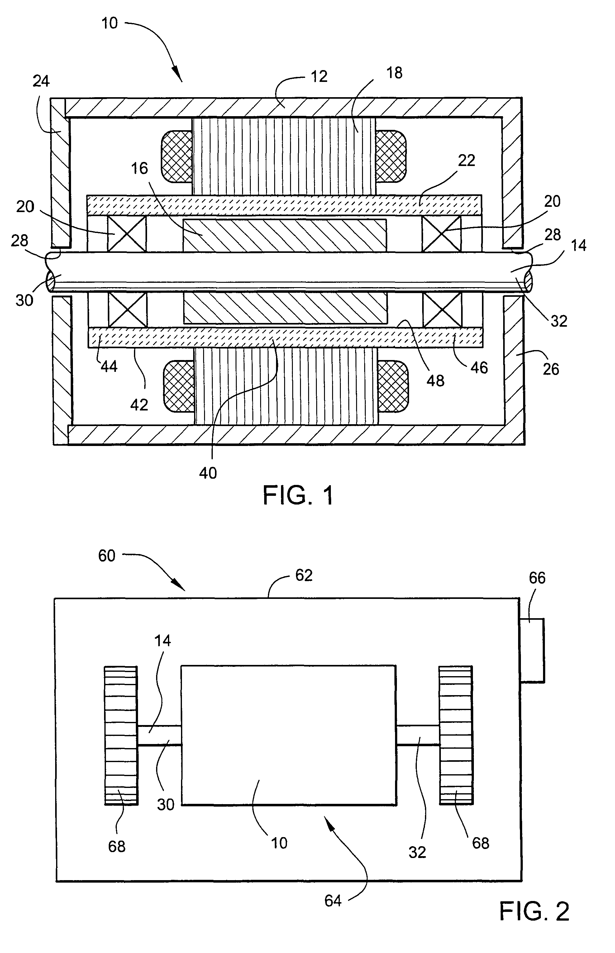
1. Electric Motor

[0042]FIG. 1 il...


PUM


Abstract

A brushless DC motor including a rotor, a magnet provided to the rotor, a pair of bearings to rotatably support the rotor, a stator assembly that at least partly surrounds the rotor and magnet thereof and adapted to control movement of the rotor, and a bearing tube having an exterior surface and an interior surface that defines a tube interior. The stator assembly is provided along the exterior surface of the tube and the bearings are provided along the interior surface of the tube to support the rotor and magnet within the tube interior. The motor has sample application for use in PAP devices for delivery of positive airway pressure therapy for users or patients.

Description

CROSS-REFERENCE TO APPLICATIONS[0001]This application is the U.S. national phase of International Application No. PCT / US2007 / 022474, filed Oct. 24, 2007, which designated the U.S. and claims the benefit of U.S. Provisional Application Nos. 60 / 853,778, filed Oct. 24, 2006, and 60 / 929,558, filed Jul. 3, 2007, each of which is incorporated herein by reference in its entirety.FIELD OF THE INVENTION[0002]The present invention relates to electric motors, and more particularly to bearing supported rotors of the electric motor. The present invention also relates to electric motors for positive airway pressure (PAP) devices or flow generators used for treatment, e.g., of Sleep Disordered Breathing (SDB) with Non-Invasive Positive Pressure Ventilation (NIPPV).BACKGROUND OF THE INVENTION[0003]Bearings are usually employed in pairs and in coaxial arrangements to support a rotating member, e.g., motor shaft. Ideally, the two bearings are located by a stationary member that constrains the two bea...

Claims


Application Information

Patent Timeline
Patent Type & Authority Patents(United States)
IPC IPC(8): H02K21/14H02K5/16
CPCH02K5/1732A61M2205/42A61M16/0066H02K7/083H02K5/128A61M16/00A61M16/021H02K5/24H02K9/14
Inventor SEARS, DAVID B.NAGORNY, ALEKSANDRMEBASSER, SAMUEL AZIZ
Owner RESMED MOTOR TECH
Why Eureka
Try Eureka