Flow control valve for dispensing a source of fluid

a flow control valve and fluid technology, applied in the direction of venting means, domestic applications, packaging, etc., can solve the problems of affecting the commercial value of products, drinking vessels that have not been reliably sealed and therefore leakage, and products that have experienced other problems

Active Publication Date: 2014-02-04
ZAK DESIGNS
View PDF7 Cites 30 Cited by
  • Summary
  • Abstract
  • Description
  • Claims
  • Application Information

AI Technical Summary

Benefits of technology

[0003]In this art field, much effort has been undertaken to design various removable lids, closure devices or other mechanisms for opening and closing a drinking or fluid dispensing orifice so as to allow the convenient dispensing of the source of fluid contained within the drinking vessel, and further, to prohibit the spilling of the fluid contained within the drinking vessel should it be accidentally overturned.
[0009]These and other aspects of the present invention will be described in greater detail hereinafter.

Problems solved by technology

While the aforementioned prior art devices have operated with varying degrees of success, there are perceived shortcomings with their individual designs which have detracted from the commercial usefulness.
For example, in some of the prior art drinking vessels utilized heretofore, such drinking vessels have not sealed reliably and therefore leak when the drinking vessel is accidentally overturned, such as might be occasioned when the drinking vessel is being used in an automobile or being carried in a backpack, or similar personally carried luggage.
While attempts have been made to correct the readily apparent shortcomings in these designs, the resulting products have experienced still other problems.
Chief among these additional problems is that these previous attempts to produce fluid impervious drinking lids or covers have usually resulted in the manufacture of products having rather complex designs.
While these improved lids, or covers, have operated with some degree of success, the complex designs of these resulting covers have made them burdensome and costly to manufacture.
Further, these rather complex designs have proven to be either difficult, or impossible to effectively clean.
Consequently, after prolonged use, or after the drinking vessel has been used for a period of time with a drink which contains sugar, or the like, such operating parts of these drinking vessel lids or covers become sticky and then begin to malfunction.
Still further, the sticky residue resulting from the fluid which is deposited on such operating parts of these prior art drinking lids create an unsanitary condition which eventually renders the drinking vessel lid or top unserviceable.

Method used


Image

  • Flow control valve for dispensing a source of fluid
  • Flow control valve for dispensing a source of fluid
  • Flow control valve for dispensing a source of fluid

Examples


Embodiment Construction

[0019]This disclosure of the invention is submitted in furtherance of the constitutional purposes of the U.S. Patent laws “to promote the progress of science and the useful arts” [Article I, Section 8].

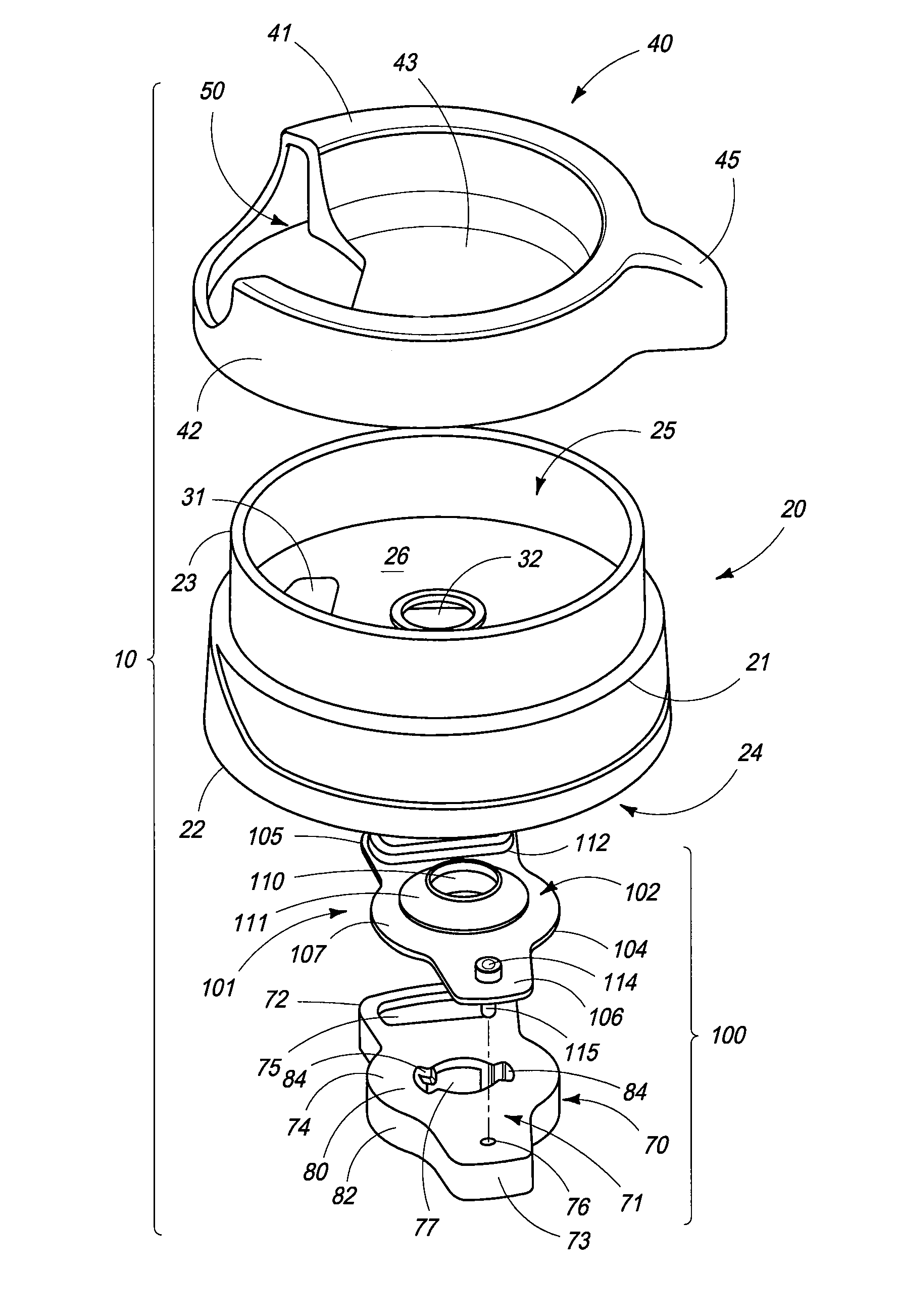
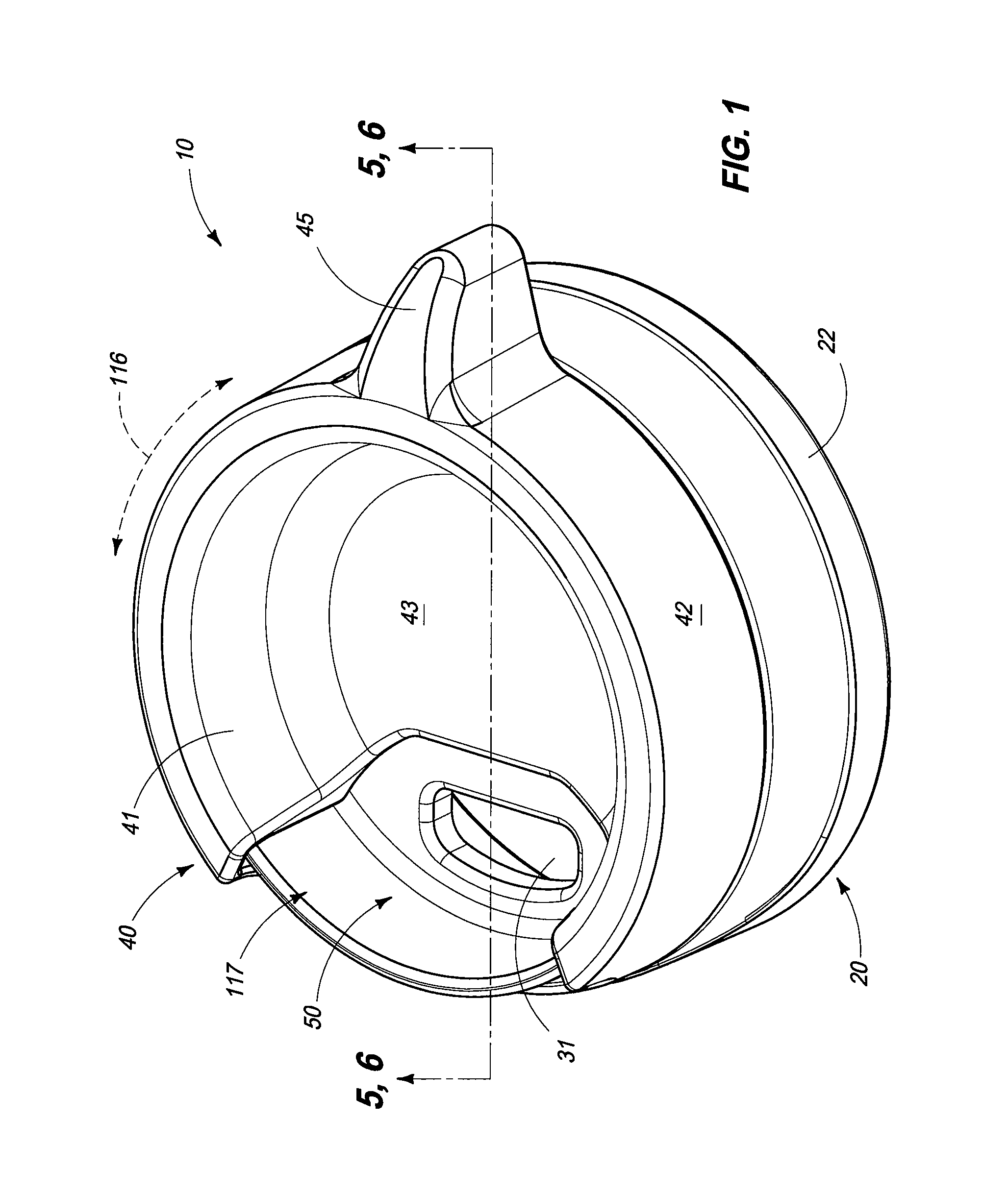
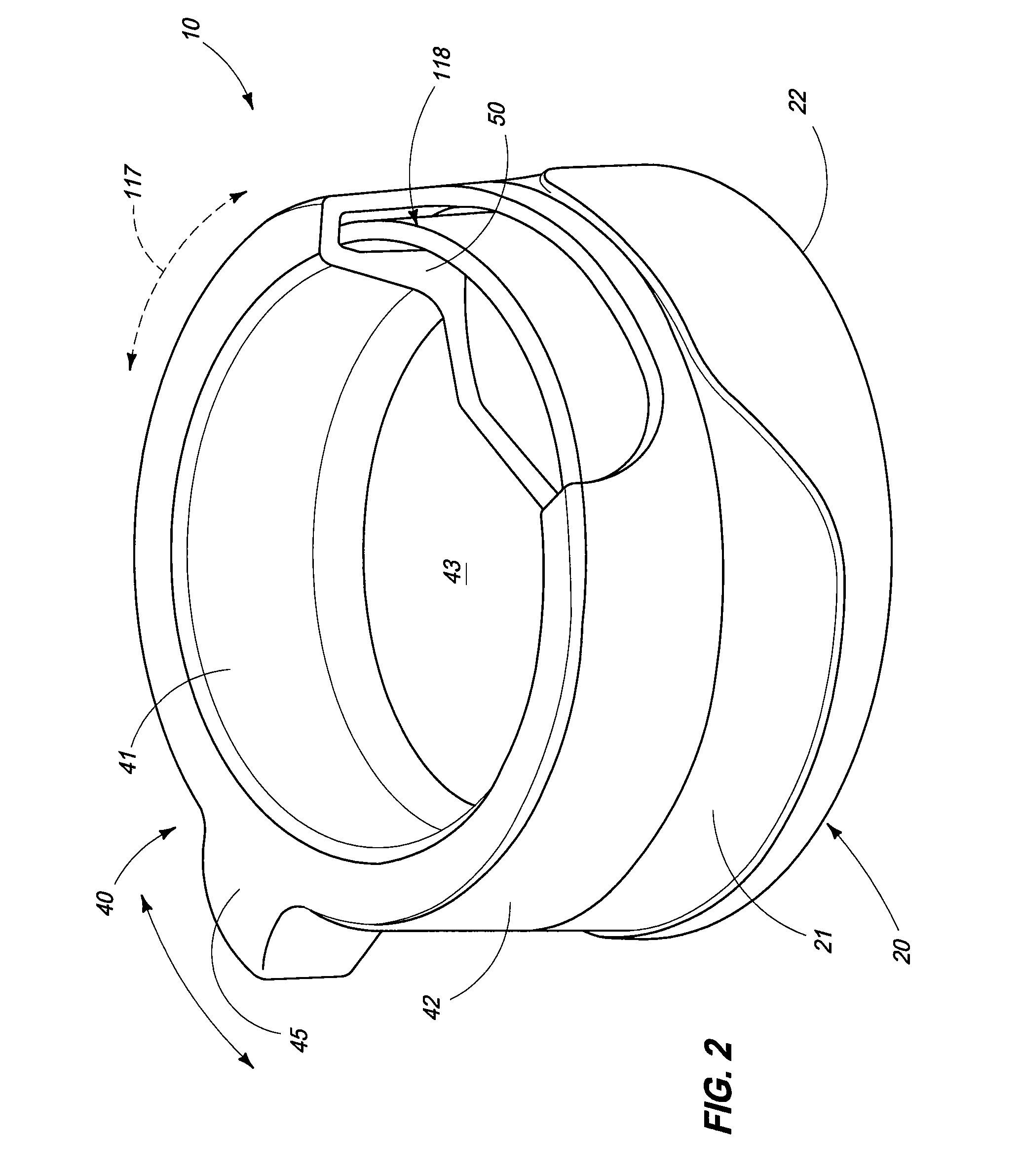
[0020]Present invention is generally indicated by the numeral 10 and is best understood by studying FIG. 1, and following. As best understood by a study of FIG. 7, the flow control valve 10 is shown as it would typically be employed on a vessel 11, of traditional design. The vessel 11 is defined by a main body 12 having a bottom surface 13. A continuous sidewall 14 extends generally upwardly from the bottom surface, and terminates in a reduced dimensioned neck region 15, which may be threaded, in order to facilitate the attachment of the neck 15 to a mating lid which incorporates the present invention. It will be understood that while the neck 15 is shown in a threaded configuration or arrangement, other types of attachment means may be used in the neck region 15 in order to readily, ...


PUM


Abstract

A flow control valve is described and which includes a first portion, and a second portion, and wherein the first portion rotates relative to the second portion and wherein the invention further includes a rigid locking member which cooperates with a resilient sealing and biasing member which is carried to positions which, on the one hand, either seals the vessel to prevent the escape of fluid from the vessel, or which allows the convenient dispensing of fluid from the vessel.

Description

TECHNICAL FIELD[0001]The present invention relates to a flow control valve for dispensing a source of fluid, and more specifically to a novel arrangement for sealing and unsealing a drinking vessel, and which further prohibits the inadvertent dispensing of fluid contained within the drinking vessel in the event that the drinking vessel is accidently overturned.BACKGROUND OF THE INVENTION[0002]Drinking containers or vessels of various types including travel mugs are well known in the art. Such drinking vessels have been designed for various purposes such as to be used on bicycles, while hiking, and doing various indoor and outdoor activities.[0003]In this art field, much effort has been undertaken to design various removable lids, closure devices or other mechanisms for opening and closing a drinking or fluid dispensing orifice so as to allow the convenient dispensing of the source of fluid contained within the drinking vessel, and further, to prohibit the spilling of the fluid conta...

Claims


Application Information

Patent Timeline
Patent Type & Authority Patents(United States)
IPC IPC(8): A47G19/22B65D51/18
CPCB65D2205/02B65D47/265
Inventor STEININGER, JEFFMALARA, NICK
Owner ZAK DESIGNS
Why Eureka
Try Eureka