Pulse abnormality detecting device

a technology of abnormality detection and detecting device, which is applied in the field of pulse abnormality detection apparatus, can solve problems such as difficulty in accurately detecting pulses, and achieve the effects of simple structure, low cost, and easy adjustment of the position of pulse sensors

Inactive Publication Date: 2014-02-11
THE MATSUMOTO INST OF LEADING EDGE OF TECH
View PDF18 Cites 2 Cited by
  • Summary
  • Abstract
  • Description
  • Claims
  • Application Information

AI Technical Summary

Benefits of technology

[0004]The present invention has been proposed in view of the above-described problems, and its object is to provide a pulse abnormality detection apparatus capable of accurately detecting a user's pulse with high precision while adapting to individual differences.
[0021]Moreover, the main body of the band is provided with the pulse abnormality detector; thus, a pulse abnormality can be recognized by the main body of the band, and the user wearing the band, for example, can recognize a pulse abnormality on the spot.

Problems solved by technology

Specifically, since a wrist has two large arteries such as a radial artery and an ulnar artery, pulses of both of radial and ulnar arteries are detected if the pulse sensor is merely placed at a position at which a pulsation of the wrist is simply detectable, and frequency change and / or phase change are / is caused in detected pulses, thus making it difficult to accurately detect pulses.

Method used


Image

  • Pulse abnormality detecting device
  • Pulse abnormality detecting device
  • Pulse abnormality detecting device

Examples


first embodiment

[0032][Pulse Abnormality Detection Apparatus of First Embodiment]

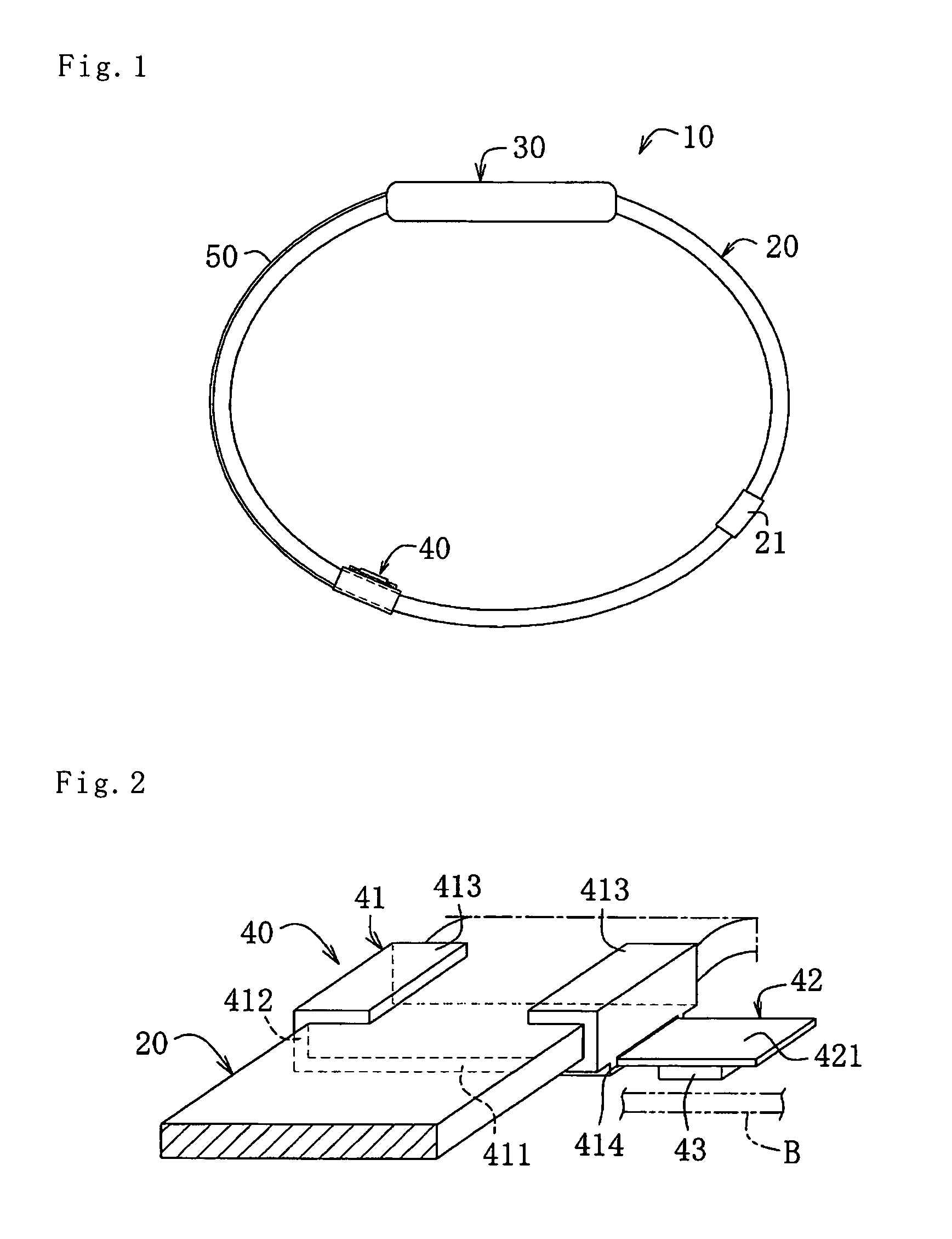
[0033]As illustrated in FIG. 1, a pulse abnormality detection apparatus 10 according to a first embodiment includes: a substantially annular strap-like band 20 worn around a user's wrist with the use of a connection made by an attachable / detachable connector 21; a main body 30 which is provided so as to be attached to the band 20 and in which a pulse abnormality detector is contained; a sensor means 40 provided so as to be slidable along the band 20; and a connection line 50 for establishing an electric connection between the main body 30 and a pulse sensor 43 of the sensor means 40.

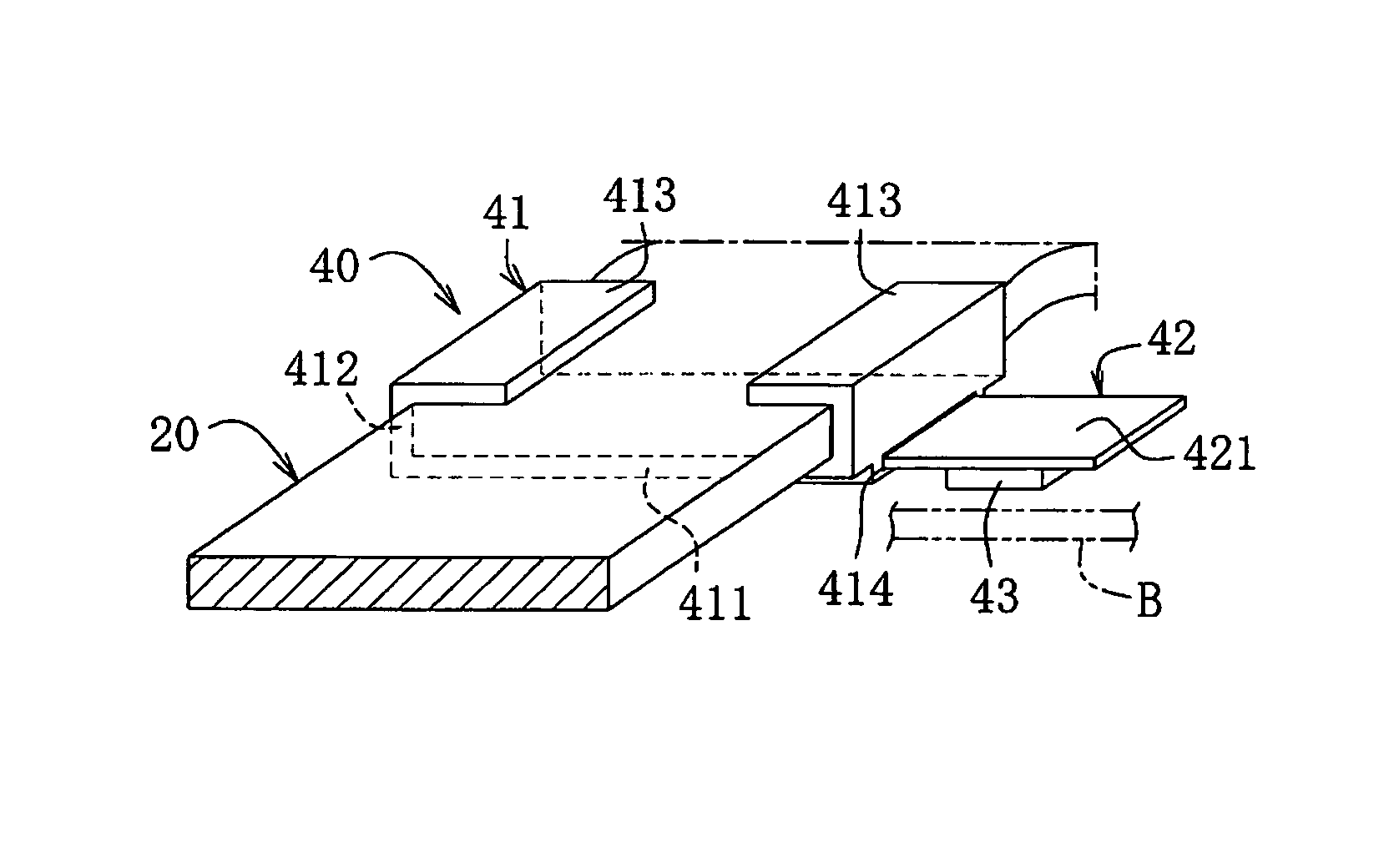
[0034]As illustrated in FIGS. 2 and 3, the sensor means 40 has: a first slide body 41 that is externally attached to the band 20 and that slides along the band 20; a second slide body 42 that is slidably provided at the first slide body 41 and that slides in an axial direction of the band 20; and the pulse sensor 43 provided on the second s...

second embodiment

[0045][Pulse Abnormality Detection Apparatus of Second Embodiment ]

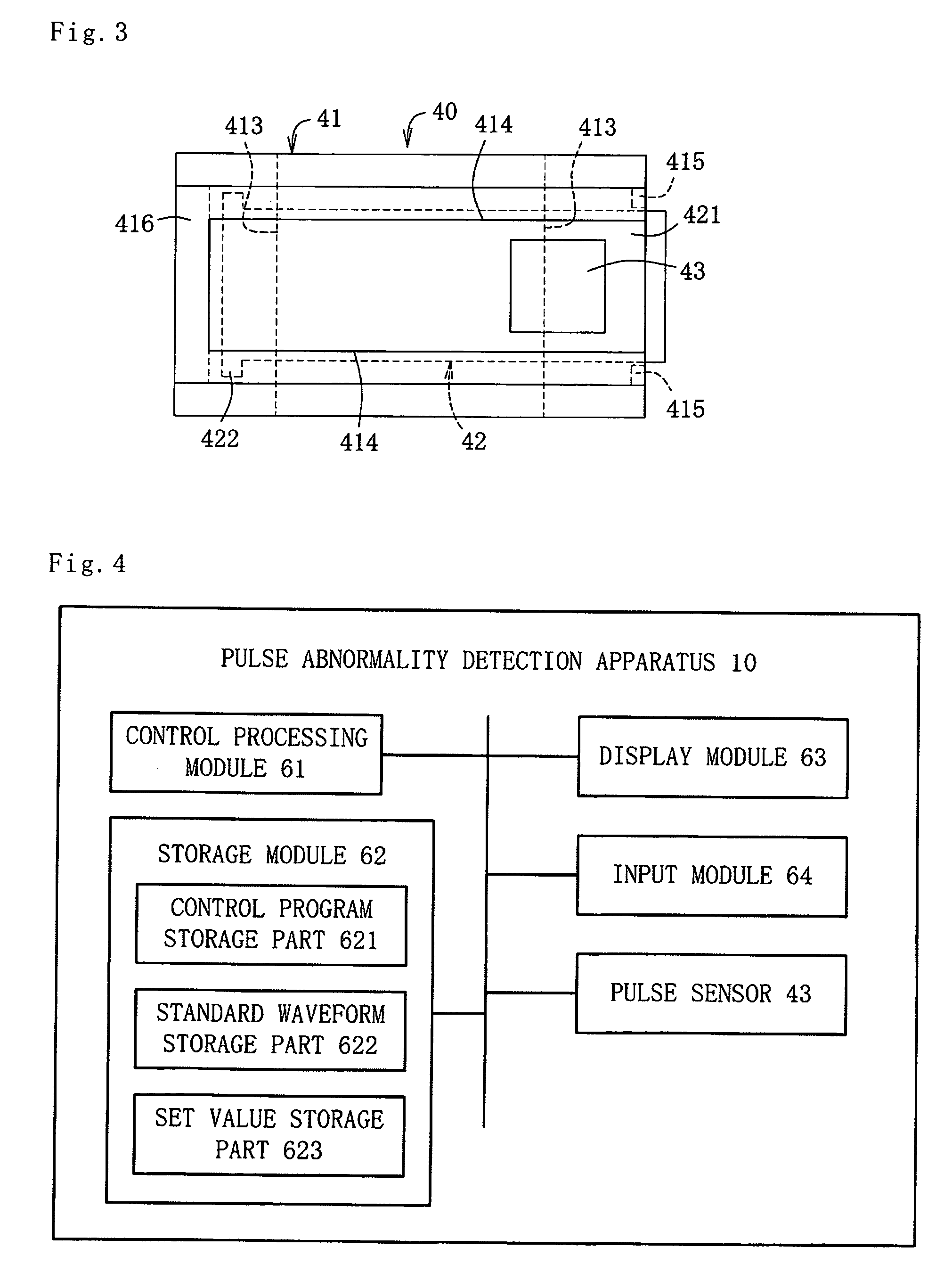
[0046]A pulse abnormality detection apparatus 10 according to a second embodiment has a structure similar to that of the pulse abnormality detection apparatus illustrated in FIG. 1, and thus has: a substantially annular strap-like band 20 worn around a user's wrist with the use of a connection made by an attachable / detachable connector 21; a main body 30 provided so as to be attached to the band 20; a sensor means 40 provided so as to be slidable along the band 20; and a connection line 50 for establishing an electric connection between the main body 30 and a pulse sensor 43 of the sensor means 40. However, a pulse abnormality detector is not provided in the main body 30, and a receiving terminal 70, wirelessly communicably connected to the pulse abnormality detection apparatus 10 or the main body 30, is provided with a control processing module 71 and a storage module 72 which correspond to the pulse abnormality det...


PUM


Abstract

A pulse abnormality detecting device comprises a band attached to a wrist, a first sliding member with which the band is armored and which slides in the circumference direction of the band along the band, a second sliding member which is slidably provided on the first sliding member and which slides in the axis direction of the band, a pulse sensor which is provided on the second sliding member and which is provided in such a manner that the position of the sensor can be adjusted to the inner side or the side of the band, and a pulse abnormality detecting unit for detecting the abnormality of the pulse from the output data of the pulse sensor. The device can accurately detect the pulse of a user with high precision, adapting to a personal difference.

Description

TECHNICAL FIELD[0001]The present invention relates to pulse abnormality detection apparatuses for detecting pulse abnormalities of users.BACKGROUND ART[0002]Examples of pulse abnormality detection apparatuses for detecting pulse abnormalities of users include a medical watch disclosed in Patent Document 1 (Japanese Unexamined Patent Application Publication No. 5-52975). In the medical watch, a pulse sensor is fixed at a given position inwardly of a wristwatch band so as to be brought into intimate contact with a position at which a pulsation of a wrist wearing the medical watch is detectable, a temperature sensor for detecting a body temperature is fixed at a given position inwardly of the wristwatch band, and outputs of these sensors are supplied to a controller. The controller compares an output waveform from the pulse sensor with a standard waveform, stored in advance, to perform blinking display on a display module and / or issue an alarm when the comparison result falls outside a...

Claims


Application Information

Patent Timeline
Patent Type & Authority Patents(United States)
IPC IPC(8): A61B5/024
CPCA61B5/02438A61B5/681
Inventor MATSUMOTO, HIROSHIKOMATSU, KAZUKO
Owner THE MATSUMOTO INST OF LEADING EDGE OF TECH
Why Eureka
Try Eureka