Multi-directionally adjustable control pods

a control pod and multi-directional technology, applied in the direction of mechanical control devices, manual control with single controlling member, instruments, etc., can solve the problems of difficult to provide uniformly comfortable and ergonomic operating positions for each operator in all operating situations, and directly affect both productivity and safety

Active Publication Date: 2014-02-18
CATERPILLAR INC
View PDF15 Cites 7 Cited by
  • Summary
  • Abstract
  • Description
  • Claims
  • Application Information

AI Technical Summary

Benefits of technology

[0010]Another machine is disclosed that also has a fore-aft centerline and a position-adjustable, dual-pod control system. The machine may include a floor, a horizontal cross beam, a pair of brackets, a pair of bearings, a pair of end plates, a pair of pod arms, a swivel, a pair of linkages, a pair of pull cables, a pair of gas struts and a foot pedal assembly. The floor includes a top side and a bottom side. The cross beam may be disposed below the floor and substantially perpendicular to the fore-aft centerline. The cross beam may also be coupled between a pair of brackets. Each pod arm may include a top and a bottom wherein the bottom of each pod arm may be sandwiched between one of the brackets and one of the end plates. Each bracket may be pivotally coupled to the bottom end of its respective pod arm about parallel first axes that are at least substantially parallel to the fore-aft centerline which thereby enables the pod arms to pivot about the first axes and at least substantially perpendicular to the fore-aft centerline. Each bracket and each bottom end of each pod arm may also include coaxial through holes that accommodate one of the bearings. The pair of bearings may be coaxially aligned along a second axis that is at least substantially perpendicular to the fore-aft centerline. As a result, the cross beam, brackets, end plates and pod arms may pivot about the second axis and at least substantially parallel to the fore-aft centerline. The bearings may be disposed opposite the floor from the cross beam. The cross beam may be pivotally coupled to the swivel about a vertical axis. The swivel may include two ends. Each end of the swivel may be coupled to one of the linkages. The linkages may extend in opposite directions from the swivel and connect one end of the swivel to one of the end plates and the other end of the swivel to the other end plate. Each strut may include a releasable locking mechanism. One of the struts may be vertically aligned with one of the pod arms and coupled between said one of the pod arms and the floor. The other strut may be coupled between the swivel and the cross beam below the floor. Each releasable locking mechanism may be coupled to a pull cable and each pull cable is coupled to a bottom portion of the foot pedal assembly, which may be disposed below the floor but which also includes a top grip portion that is disposed above the floor. As a result, depressing the top portion of the foot pedal assembly pulls the pull cables which unlock both releasable locking mechanisms. Further, pivotal movement of the top end of one of the pod arms in a first direction that is perpendicular to the fore-aft centerline (either towards or away from the fore-aft centerline) may cause the bottom end of the pod arm to pull or push its respective linkage in an opposite second direction thereby causing the swivel to pivot about the vertical axis and push the other linkage in the first direction and pivot the top end of the other pod arm in the second opposite direction. Thus, the pod arms may be moved towards or away from each other. Further, pivotal movement of one of the pod arms in a third direction that is parallel to the fore-aft centerline may cause both pod arms and brackets to pivot parallel to the third direction and parallel to the fore-aft centerline.

Problems solved by technology

As a result, consistently comfortable and ergonomic operating positions for each operator for all operating situations is difficult to provide.
Further, because an operator must use both right hand and left hand control pods and because the control pods are sensitive, the comfort and ergonomics of the operator's position can directly affect both productivity and safety.

Method used


Image

  • Multi-directionally adjustable control pods
  • Multi-directionally adjustable control pods
  • Multi-directionally adjustable control pods

Examples


Embodiment Construction

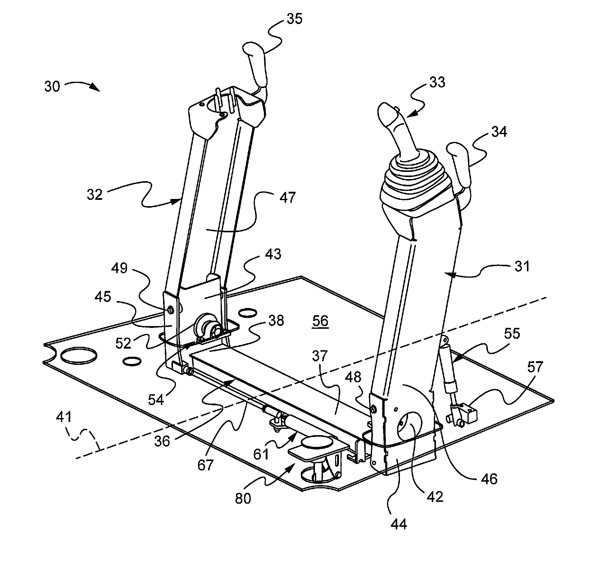
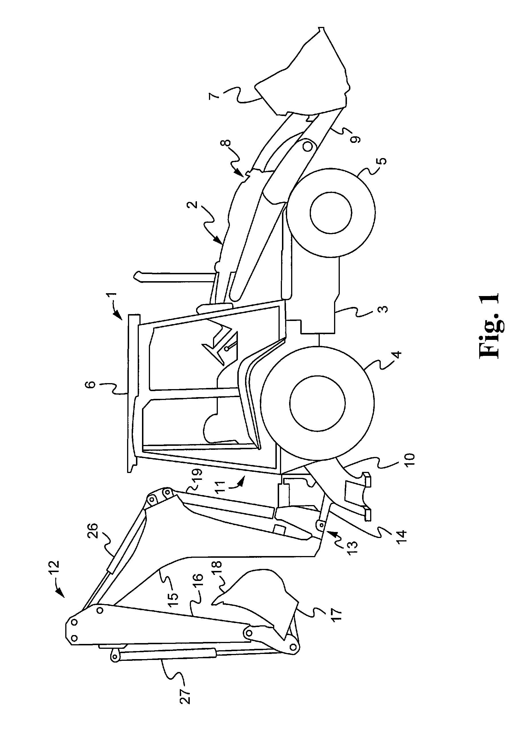
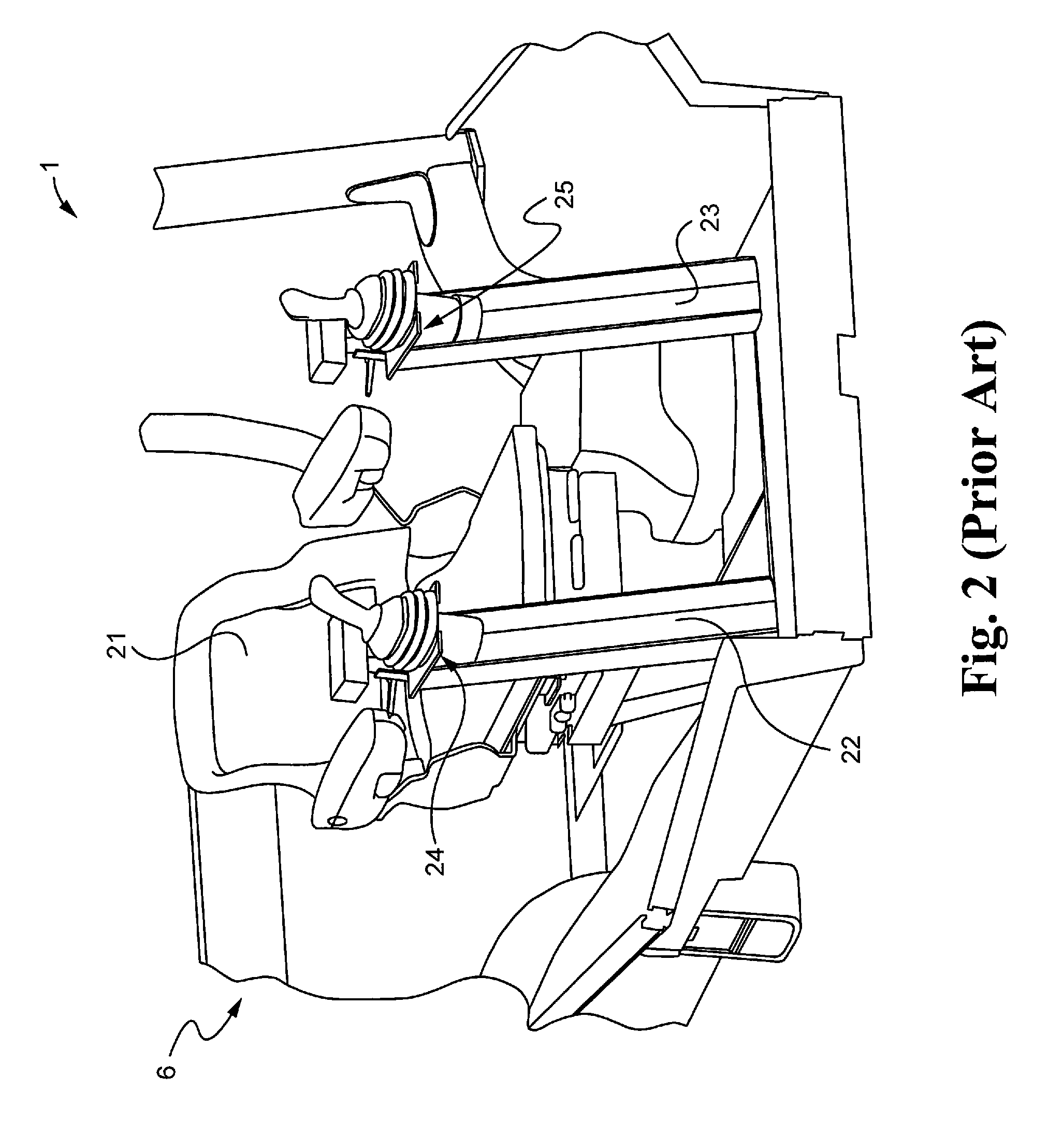
[0022]FIG. 1 illustrates an exemplary backhoe loader 1 that may be employed in connection with embodiments of the disclosure. Backhoe loader 1 may include a machine, such as a tractor 2, having a chassis 3. The tractor 2 may include ground elements, such as a pair of rear wheels 4 and a pair of front wheels 5. It should be understood that, instead of wheels 4, 5, the tractor 2 could be provided with a pair of tracks or other structure to permit transportation of the tractor. Backhoe loader 1 may also include a cab 6 or other suitable facilities to accommodate an operator (not shown). The cab 6 may include suitable controls for controlling operation of the backhoe loader 1. For example, the controls may include joysticks 24, 25 as shown in FIG. 2 for enabling the operator to interface with the control system of the machine.

[0023]The backhoe loader 1 may include a loader bucket 7 at a first end 8 of the tractor 2, and suitable operating linkage 9 for manipulation of the loader bucket ...


PUM


Abstract

A position-adjustable, dual-pod control system for a machine, such as a backhoe loader is disclosed. The system includes a horizontal cross beam connected to a pair of brackets. The pair of brackets are mounted to the machine by way of a pair of bearings that enables pivotal movement of the cross beam in the fore and aft directions while the cross beam is positioned perpendicularly to the fore and aft direction or the fore-aft centerline of the machine. The bottom end of each pod arm is pivotally coupled to the brackets thereby enabling the pod arms to be pivoted towards or away from the centerline. Each bracket includes a through hole that accommodates a bearing that is mounted to the machine, such as to the floor of the machine.

Description

TECHNICAL FIELD[0001]This disclosure relates generally to an implement control system for a machine, such as a backhoe loader, that is adjustable in at least two directions for the comfort and ease of use of operators of varying heights, weights and body shapes.BACKGROUND[0002]Many machines have been developed for excavating. One commercially available type of machine often used for excavating is a backhoe loader. Generally, a backhoe loader includes a backhoe mounted on a tractor or other machine body that is moveable along the ground on wheels or tracks. The backhoe may be the only excavating implement on the tractor or machine body, or it may be one of a plurality of implements. For example, a backhoe loader may include a backhoe mounted at one end of a tractor and a loader bucket mounted at the other end of the tractor. Stabilizing legs may also be included to hold the tractor in place while the operator is digging with the backhoe.[0003]A typical backhoe loader may include a bo...

Claims


Application Information

Patent Timeline
Patent Type & Authority Patents(United States)
IPC IPC(8): B60K26/00
CPCE02F9/2004E02F3/964G05G9/047Y10T74/20372
Inventor CONNOR, ALAN ROBERTHEALD, RICHARD ADAM KENNETHBOWER, ROBERT MICHAELSHEEHAN, PAUL ANTHONY
Owner CATERPILLAR INC
Why Eureka
Try Eureka