Device management system

a technology of device management and management system, applied in the field of device management system, can solve the problems of not maintaining the management of slave units and the inability to maintain the management of devices

Inactive Publication Date: 2014-02-18
PANASONIC CORP
View PDF8 Cites 0 Cited by
  • Summary
  • Abstract
  • Description
  • Claims
  • Application Information

AI Technical Summary

Benefits of technology

[0004]It is an object of the present invention to provide a device management system which can maintain a management of a slave unit had been managed by a master unit until then even if the master unit malfunctions.
[0008]In this configuration, when the second master unit malfunctions, the first master unit and the second communication network are connected with the connection unit, and thereby the first master unit can communicate with the second slave unit with which the second master unit had communicated until then. As a result, the device management system can maintain to manage without stopping to communicate with the second slave unit even if the second master unit malfunctions.
[0018]In this configuration, the detector separated from each of the master units has a detecting function, and there is no need for each of the master units to comprise the detecting means. Therefore, load of each of the master units can be decreased, compared with the master units of which each has the detecting means.

Problems solved by technology

However, if the master unit malfunctions, such old device management system can not maintain a management of a slave unit which had been managed by the master unit until then.
As a result, the old device management system has a problem that the slave unit (which had been managed by the malfunctioning master unit) can not maintain managements of devices had been managed until then.

Method used


Image

  • Device management system
  • Device management system
  • Device management system

Examples


first embodiment

(First Embodiment)

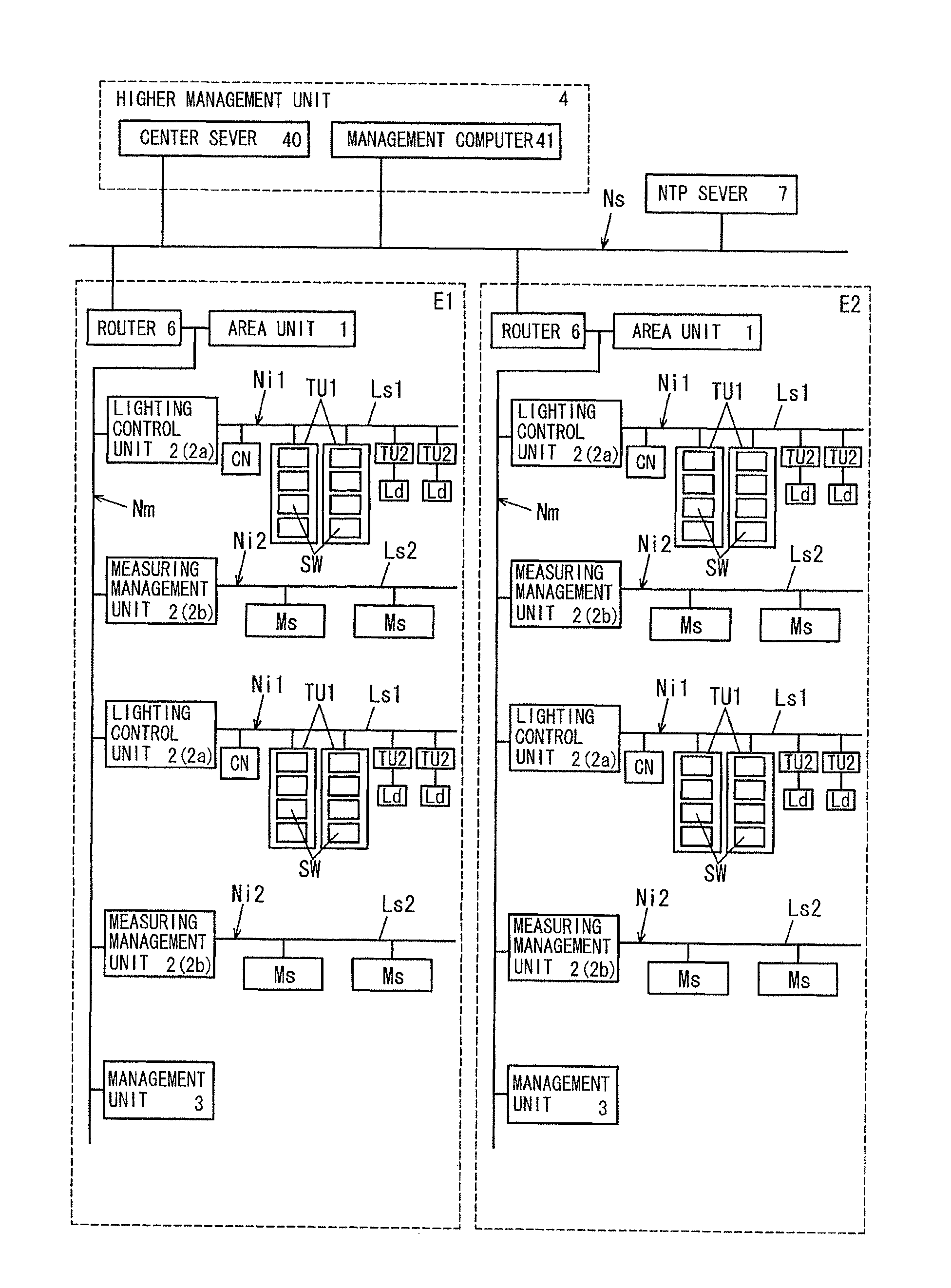
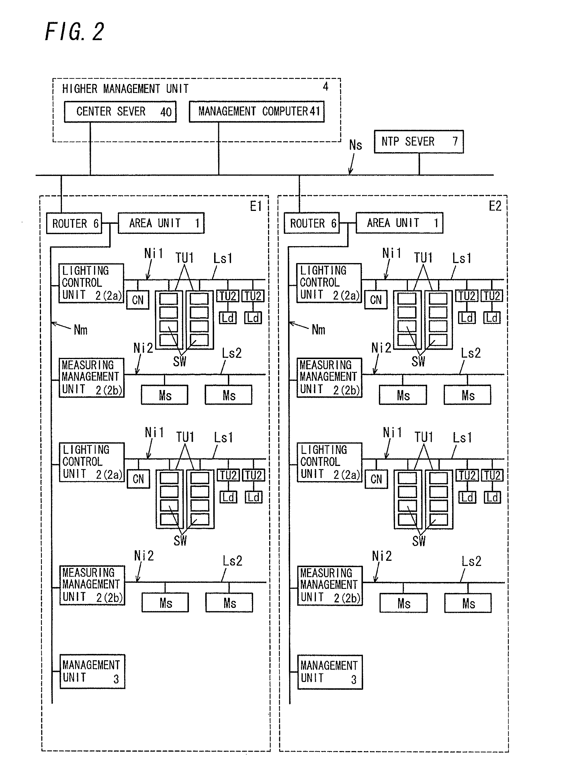
[0038]In the present invention, monitoring and controlling operations of various types of devices are called “management” of device. Thus, the management of the device means at least either of monitoring or controlling. Then, an entire region, in which managed devices are located, is called “management region” in the present invention. When the management region is divided into a plurality of small regions, one of the small regions is called “area”.

[0039]The management region is a widely-separated space and corresponds to a space in which many devices are located. The devices are lighting devices, or cooling and heating devices, etc. The widely-separated space is a space like various buildings, a site of multiple dwelling, a group of residential area, a theme park, or a park, etc. The various buildings are an office building, a collective housing, a hospital, a school, a hotel, a gymnasium, an art gallery, a museum, and a shopping center, etc. A plurality of buildi...

second embodiment

(Second Embodiment)

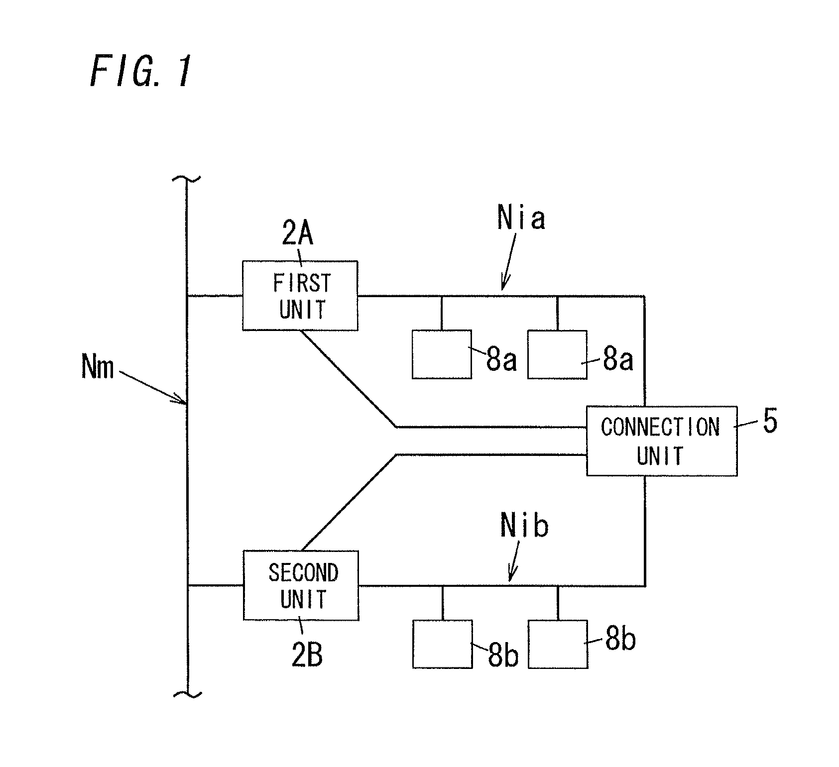
[0070]By the way, when the second unit 2B shown in FIG. 1 malfunctions and the first unit 2A communicates with the second device 8b connected to the lower net Nib, the same communication address may be set to the first device 8a connected to the lower net Nia and the second device 8b.

[0071]Similarly, when the first unit 2A malfunctions and the second unit 2B communicates with the first device 8a, the same communication address may be set to the first and second devices 8a, 8b.

[0072]So, in a device management system of a second embodiment, the signal processor 24 of each unit 2 (the first unit 2A, the second unit 2B) has a function to translate communication addresses of the first and second devices 8a, 8b. The signal processor 24 of the present embodiment is equivalent to an address translation means of the present invention. In addition, the same composition elements as the first embodiment are putted the same numerals on, and the explanation thereof is omitted...

third embodiment

(Third Embodiment)

[0079]In a third embodiment, a communication protocol (hereinafter called “first communication protocol”) used in the side of the first unit 2A, as shown in FIG. 1, is different from a communication protocol (hereinafter called “second communication protocol”) used in the side of the second unit 2B, and this is explained below. In the present embodiment, the first unit 2A shown in FIG. 1 is the lighting control unit 2a, and the second unit 2B is the measuring management unit 2b. In addition, the same composition elements as the first embodiment are putted the same numerals on, and the explanation thereof is omitted.

[0080]Hereinafter, the present embodiment is explained to center around the first unit 2A. The second unit 2B can be explained by translating to the phrase shown in parentheses. As shown in FIG. 9, the first unit 2A (the second unit 2B) comprises the higher communication unit 20, the memory 22, the switching signal communication unit 23, and the signal p...


PUM


Abstract

A first unit and a second unit manage a plurality of devices (a first device), respectively. In addition, the first and second units, repeat to transmit a keep-alive packet and to confirm a response each other, and thus detect each other's malfunction. When the second unit malfunctions, the first unit detects the malfunction of the second unit and transmits a connection command to the connection unit. The connection unit connects a lower net Nia and a lower net Nib when receiving the connection command. Then, the first unit communicates with the first device as heretofore, and further communicates with a second device via the connection unit. Thus, even if a master unit malfunctions, the device management system can maintain to manage without stopping a management of a slave unit which had been managed by the master unit until then.

Description

TECHNICAL FIELD[0001]The present invention relates generally to device management systems, and more particularly to a device management system that manages a plurality of devices arranged and divided into a plurality of management groups.BACKGROUND ART[0002]In the past, there have been proposed various device management systems for managing (at least either of monitoring or controlling) a plurality of devices, and the device management systems construct a lower-level communication network with respect to each of management groups which are grouped in terms of kinds of devices and arranged places. The plurality of devices are arranged, and are divided into a plurality of management groups. The lower-level communication network is managed by an upper-level communication network. In order to construct such hierarchical communication network, a technology to manage a slave unit by a master unit has been used. In the technology, the slave unit for managing a device (the slave unit integr...

Claims


Application Information

Patent Timeline
Patent Type & Authority Patents(United States)
IPC IPC(8): G06F15/16G06F11/00
CPCH04L12/4625H04L12/403
Inventor SATO, TOSHITAKAKASAI, YUUKIAMANO, MASAYUKIMATSUMOTO, TADASHI
Owner PANASONIC CORP
Why Eureka
Try Eureka