Garment incorporating functional electrical circuit

Active Publication Date: 2006-10-19
NEL TECH
View PDF32 Cites 8 Cited by
  • Summary
  • Abstract
  • Description
  • Claims
  • Application Information

AI Technical Summary

Benefits of technology

[0035] In any of the aspects of the invention set out above, the flexible metallised fabric may be shaped so as to provide terminals for electrical connection of tracks formed on the fabric at an elongate flexible tail portion of the fabric. In this way, the functional part

Problems solved by technology

Ideally, such a heater could be capable of forming part of the garment

Method used


Image

  • Garment incorporating functional electrical circuit
  • Garment incorporating functional electrical circuit
  • Garment incorporating functional electrical circuit

Examples


Example

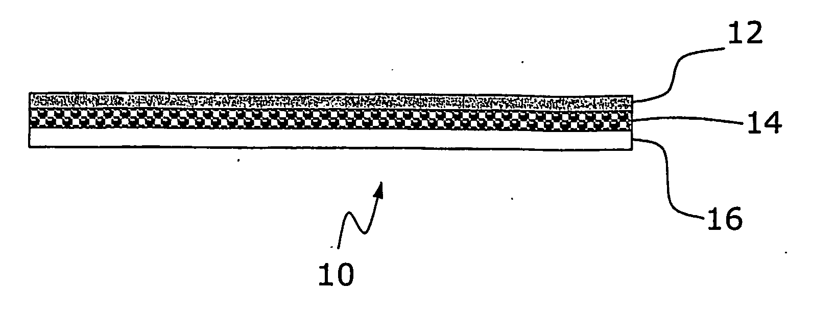
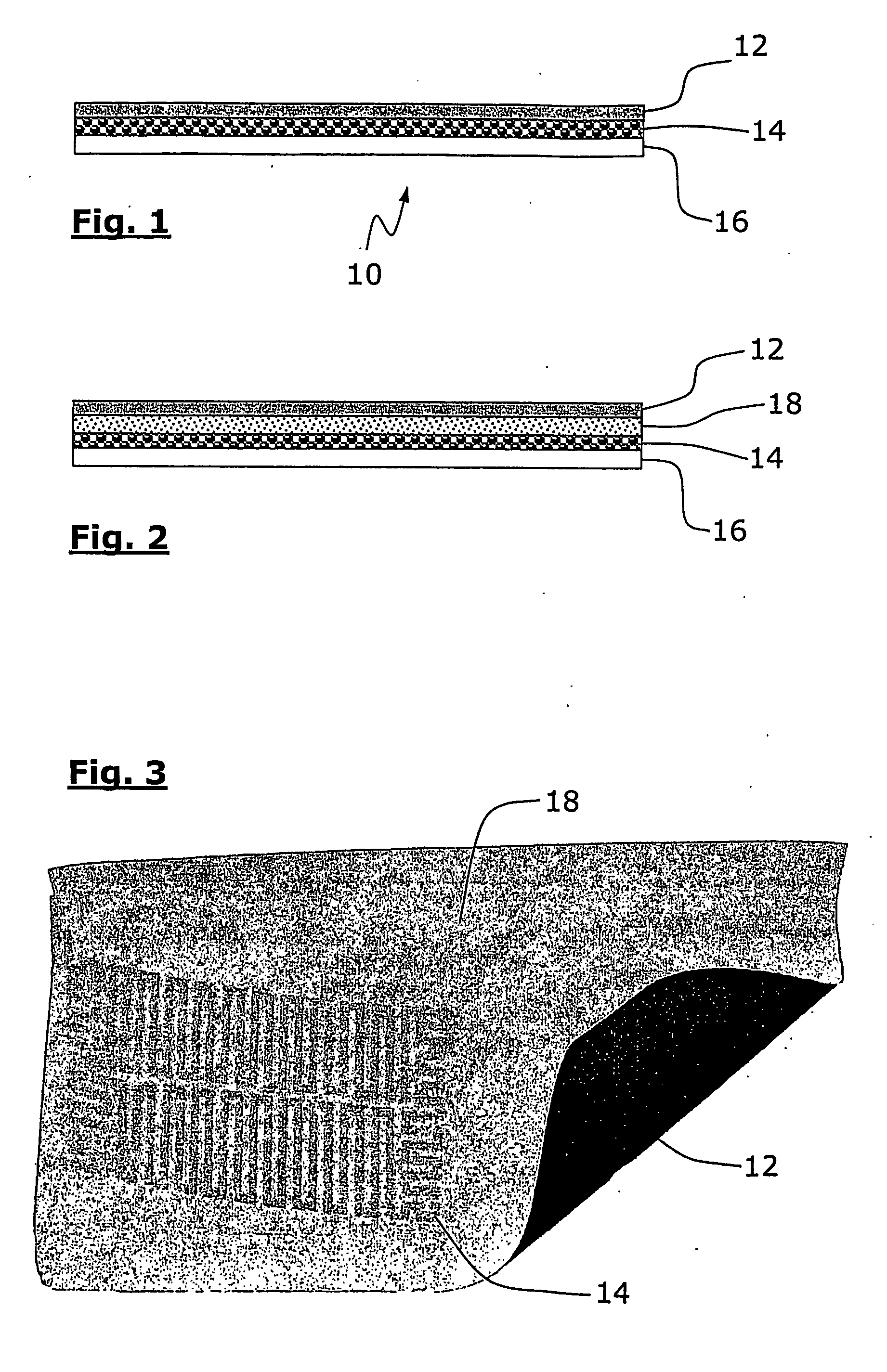
[0044]FIG. 1 shows a laminated fabric structure 10 having three layers. Heater element layer 14 is sandwiched between face fabric layer 12 and inner fabric layer 16.

[0045]FIG. 2 shows an alternative laminated fabric structure having four layers. Heater element layer 14 is sandwiched between breathable film or coating 18 and inner fabric layer 16. Face fabric layer 12 is disposed on breathable film 18.

[0046]FIG. 3 shows a schematic plan view of a laminated fabric according to an embodiment of the invention but without an inner fabric layer 16. One corner of the limited structure is shown turned over to expose the face fabric layer 12. Breathable layer 18 is disposed on the back surface of face fabric layer 12. Heater element layer 14 is located on the breathable layer. Inner fabric layer 16 is not shown for the sake of clarity.

[0047] A suitable power supply (not shown) for the heater is supplied by Mpower Batteries Limited, consisting of 2×3.6 V lithium ion batteries. Suitable con...


PUM


Abstract

Disclosed is a breathable heater element for a garment or for the lining of a garment such as an outdoor jacket, e.g. a waterproof jacket. The heater element is formed from porous metallised fabric such a nickel plated woven polyester fabric by photochemical etching of a suitable track pattern onto the metallised fabric. The formed heater element is then laminated into a lining. The material of the lining may be impregnated with microencapsulated functional chemicals such as fragrances, perfumes, antimicrobials or insect repellents. The microcapsules release their contents on activation due to heat generated by the heater element.

Description

BACKGROUND TO THE INVENTION [0001] 1. Field of the Invention [0002] The present invention relates to a garment or garments incorporating a functional electrical or electronic circuit. Preferably, the invention relates to the incorporation into a garment of a breathable, porous, flexible fabric circuit for use as a heater. The garment may include a thermally activated chemical delivery system. The circuit may be used as an electrical interconnect (electro-conductive) system with or without electronic devices, e.g. as a keypad or keyboard. [0003] 2. Related Art [0004] A primary function of garments designed for outdoor sports and leisure activities such as mountaineering, hiking, potholing, motorcycling, etc., is thermal protection, particularly from cold weather conditions. Similarly, such thermal protection is important in many work-wear applications (e.g. seamen, workmen, delivery personnel, refrigeration plant operators, airport workers, etc.) where, potentially, staff may be expo...

Claims


Application Information

Patent Timeline
IPC IPC(8): H05B3/34A01M1/20A61L9/03
CPCA01M1/2077A61L9/03H05B3/342H05B2203/036H05B2203/013H05B2203/017H05B2203/003
Inventor FERGUSON, PATRICK
Owner NEL TECH
Why Eureka
Try Eureka