
Method and devices for cell loss detection in ATM telecommunication devices

Inactive Publication Date: 2004-07-13
ALCATEL LUCENT CANADA +1
View PDF15 Cites 8 Cited by
  • Summary
  • Abstract
  • Description
  • Claims
  • Application Information

AI Technical Summary

Benefits of technology

Further aspects and advantages of the invention are described below.
In drawings which illustrate non-limiting embodiments of the invention:
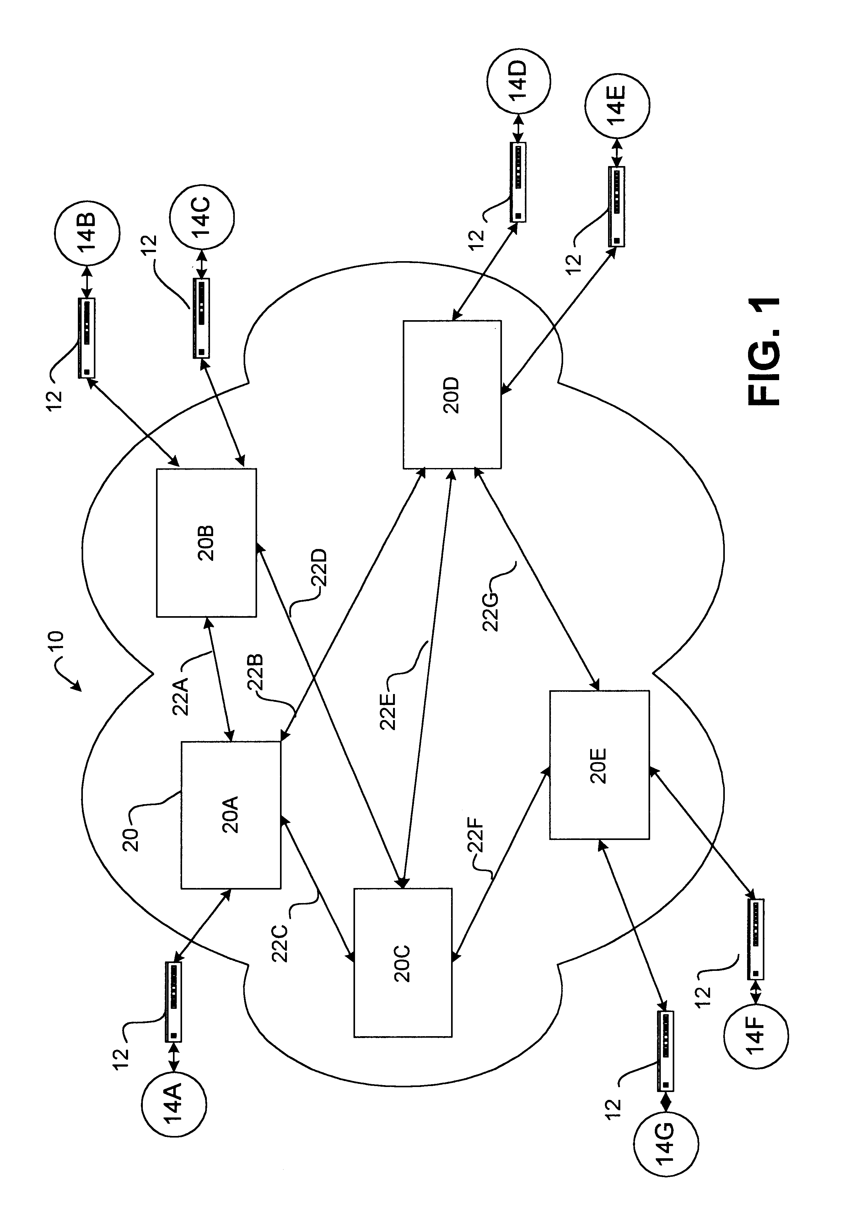
FIG. 1 is a schematic view of a prior art ATM packet switched network;
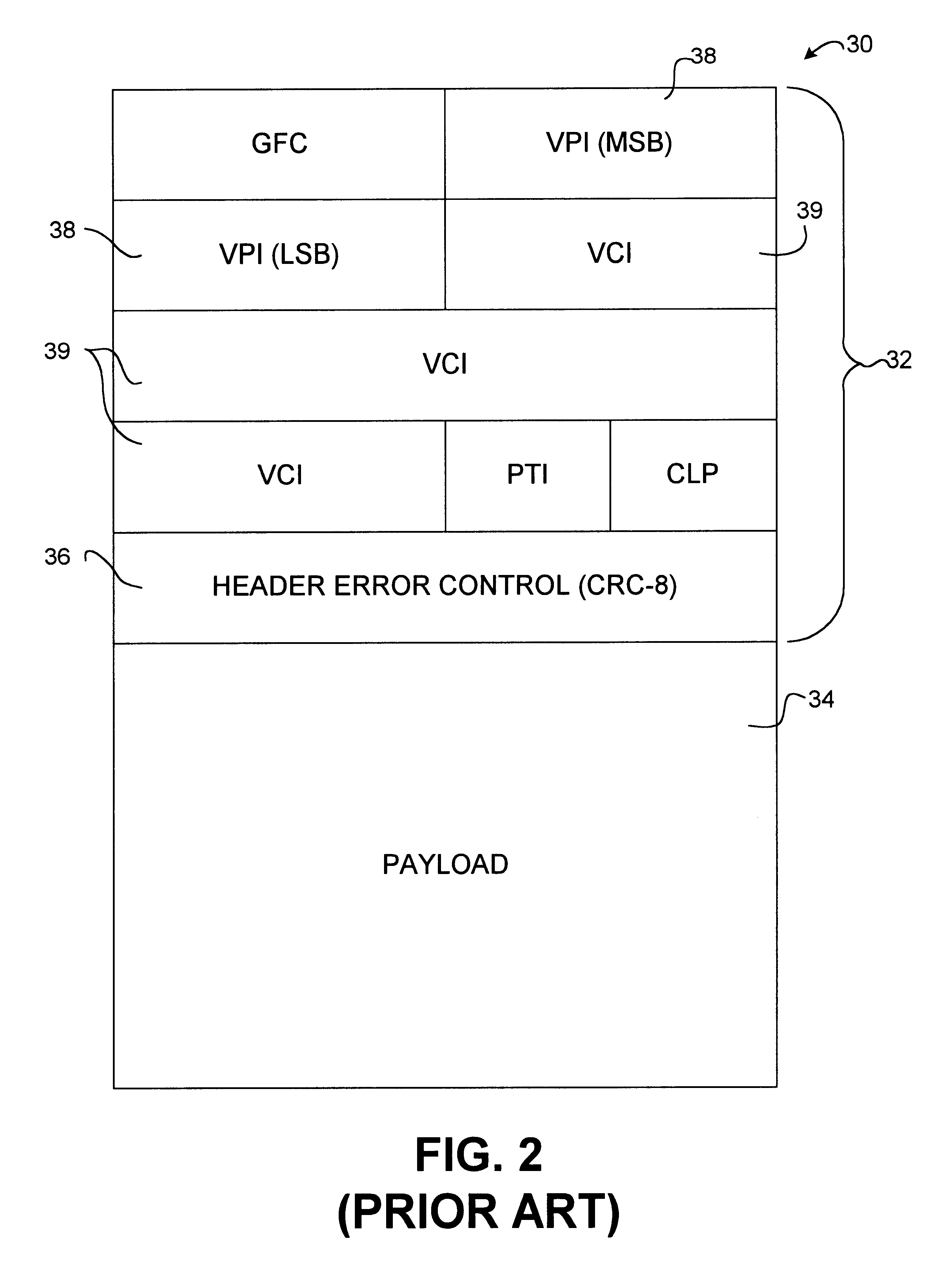
FIG. 2 is a schematic view illustrating the format of a standard ATM cell;
FIG. 3 is a block diagram illustrating the flow of ATM cells on one VC across the ATM network of FIG. 1;
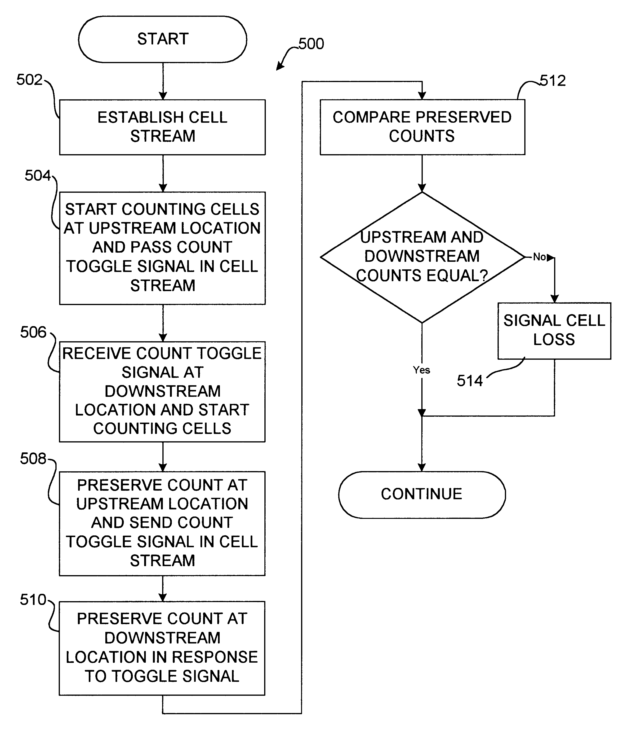
It can be appreciated that method 500 avoids the need to sample the up stream and down stream counters at exactly the same instant in time. ATM cells in a cell stream are passed along the cell str

Problems solved by technology

In any ATM network some loss of ATM cells may occur during normal operation.
UPC may refuse to accept cells in certain cell streams to prevent an ATM switch from becoming overloaded in a manner which could interfere with QoS guarantees for an existing call.
This is a problem because ATM cells can be lost internally to ATM switches, particularly when the switches are operating at extremely high data rates.
Furthermore, malfunctions in switches can cause the loss of ATM cells.
An ATM cell may be lost from a data stream if, for example, its header becomes corrupted so that the cell is no longer recognized as being part of the cell stream to which it should belong.
Unintentional cell loss is a "silent failure" which will only be detected if an end customer complains.
The problem with this approach is that there is no way to know how many cells in the cell stream for a virtual circuit are buffered within the switch at any given time.
A second problem with using ingress and egress counters to detect cell loss is a synchronization problem.
This is typically impossible where the polling of counters is controlled by software.
This, however, delays the availability of results.
The disadvantage of this approach is that it only detects cell loss when a call is completed.
The Tremel et al. device does not enable the direct detection of lost cells.
The Kawasaki et al. device does not deal with the problem that a certain number of cells will be buffered within a switch or other telecommunications device at any given time and does not operate continuously.

Method used


Image

  • Method and devices for cell loss detection in ATM telecommunication devices
  • Method and devices for cell loss detection in ATM telecommunication devices
  • Method and devices for cell loss detection in ATM telecommunication devices

Examples


example 2

Count Synchronization Signal Switches Between Counters

FIG. 8 shows a portion of a switch 20 set up according to a second exemplary embodiment of the invention. In FIG. 8, instead of a single counter for each cell stream passing through the counting device 62, there are two or more separate counters for each cell stream. In the illustrated embodiment there are two counters which are labelled for reference COUNTER A and COUNTER B. At any given time only one of the two counters is active. Which counter is active is indicated in an active counter ("AC") field within array 63. The inactive one of the two counters for each cell stream preserves the value that it had immediately before becoming inactive.

On the occurrence of a toggle event for a cell stream, counter 62 switches to the other counter for that cell stream. Synchronization setter 64 writes a value to a synchronization flag within cells in each data stream in a manner which signals to downstream synchronization detector 72 when ...

example 3

Count Synchronization Signal Carried in PM Cells

FIGS. 10 and 11 illustrate a third exemplary embodiment of the invention. In the embodiment of FIGS. 10 and 11, a synchronization signal is included in a Performance Measurement (or "PM") cell. PM cells are additional, identifiable, ATM cells which are inserted from time to time into each cell stream being monitored. In the FIG. 10 embodiment, synchronization flag setter 64 is replaced by a PM cell inserter 84. PM cell inserter 84 receives a signal from counter 62 on line 65 when a PM cell should be inserted into a cell stream. A PM cell detector 85 detects PM cells and sends a signal to counter 69 which causes counter 69 to preserve the number of cells counted in the cell stream in which the PM cell was detected since the last PM cell in that cell stream.

Two modes of operation are possible. In a first mode of operation, PM cells are periodically inserted into the cell stream in such a manner that a predetermined number of other cells ...

example 4

Sequence Numbers Provide Count Synchronization Signal

FIGS. 12 and 13 illustrate a fourth exemplary embodiment of the invention. This embodiment differs from the embodiments described above in that a counter value for each cell is delivered in the cell stream to down stream locations.

As shown in FIG. 12, apparatus 20 includes a counter 62 which counts the cells passing the counter in each cell stream and stores a sequence number in an associated array 87. A sequence number inserter 86 inserts the sequence number of each cell into the cell at an up stream location. One or more sequence number checkers 88 are located at downstream locations. Each sequence number checker 88 has a an associated array 89 for holding sequence numbers of previously received cells in each cell stream.

The apparatus 20 of FIG. 12 can be operated according to the method 1300 of FIG. 13. Method 1300 begins by receiving a cell (Step 1302) and determining the cell stream to which the cell belongs (Step 1304). A se...


PUM


Abstract

Methods and devices for detecting cell loss in telecommunication devices, such as ATM switches, attach cell loss detection information to cells in cell streams passing through the telecommunications devices. The cell loss detection information can trigger counters at up stream and down stream locations thereby avoiding the problem of synchronizing counters and ensuring that all cells to be counted have been flushed through the telecommunications device. The cell loss detection information can include a sequence number in a sequence of n sequence numbers where n is not a power of 2. Preferably n=2-1, where P is an integer. Such series of sequence numbers allow the detection of lost cells in bursts consisting of a number of lost cells which is a power of 2. The methods and apparatus of the invention permit detection of unintentionally dropped cells in a call without the need to tear down the call.

Description

This invention relates to asynchronous transfer mode ("ATM") telecommunication devices. The invention has particular application to ATM switches. The invention provides methods and devices for detecting the loss of ATM cells in one or more cell streams passing along one or more data paths in a telecommunication device.BACKGROUNDSAn ATM network is a connection-oriented packet switched network. An ATM network includes a number of ATM telecommunication devices, including ATM switches, which interconnect ATM end points via point-to-point transmission links. A "call" may be set up to provide one or more virtual connections between selected endpoints. Cell streams flow along the virtual connections from one end point on the network to another. On their way, the cell streams traverse various ATM switches and other telecommunication devices.The telecommunication devices in modern ATM networks must operate at extremely high levels of reliability at extremely high speeds. The increasing impor...

Claims


Application Information

Patent Timeline
IPC IPC(8): H04Q11/04H04L12/56
CPCH04L49/3081H04Q11/0478H04L2012/5647
Inventor LAW, RANDALL ALLANMARGERM, STEVEN DOUGLAS
Owner ALCATEL LUCENT CANADA
Learn More