

Pelvic plane locator and patient positioner
a patient positioner and locator technology, applied in the field of orthopaedic surgery, can solve the problems of wear, deformation or even fracture, extreme pain, and many procedures that will eventually require revision
- Summary
- Abstract
- Description
- Claims
- Application Information
AI Technical Summary
Benefits of technology
Problems solved by technology
Method used
Image

Examples
Embodiment Construction
[0019]The present invention preferably functions in the context of a computer assisted surgical navigation system, to which it is particularly well suited. An example of a suitable system is disclosed in U.S. Pat. No. 6,711,431.
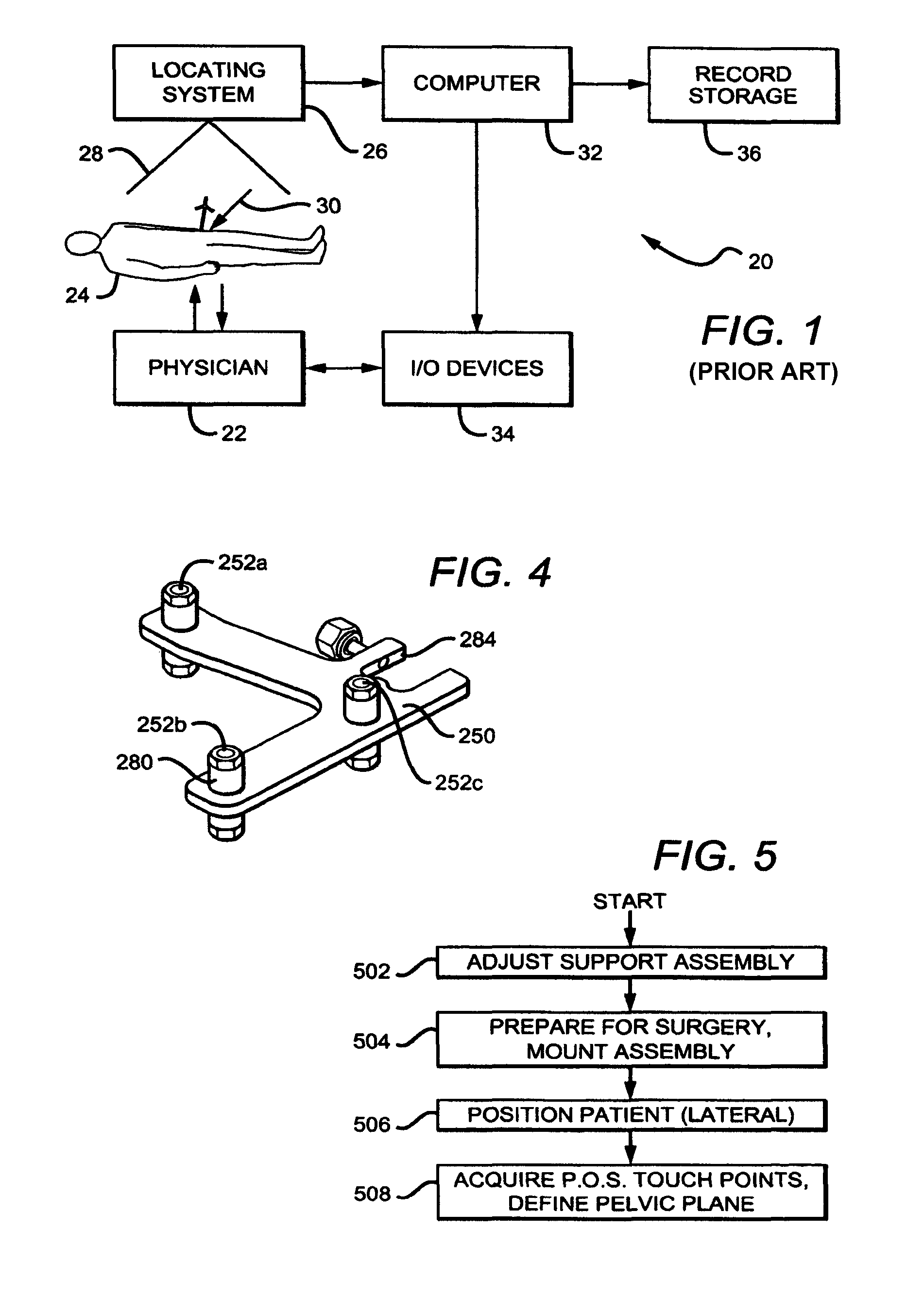
[0020]FIG. 1 shows a system-level block diagram of a prior art system or apparatus 20 which provides the preferred environment in which the present invention operates. The system or apparatus 20 is generally a computer aided system for navigating orthopedic surgery. A physician or other professional 22 performs a hip surgery (for example, total hip replacement) on a patient 24. An optical or equivalent locator or locating system 26 is disposed near the patient, so that the operating field is encompassed substantially within the field of view 28 of the locator 26. A suitable optical locator is available commercially, for example the “Polaris” available from Northern Digital Inc., in Waterloo, Ontario, Canada. Optical trackers or markers 30 are used during the ...
PUM
 Abstract
Description
Claims
Application Information